Falcon Altius Surrogate
This Interface Control Document (ICD) defines the high-level requirements to successfully interface payloads with SpektreWorks’s Falcon Altius Surrogate.
All units are in inches unless otherwise stated.
Contents
- Overview
- Main Payload
- Altius 600 Payload
- Weight and Balance
- Vibration
- Environmental Requirements
- Electrical Interface Overview
- Power
- Communications
- Connector Specs
- Pinouts
Overview
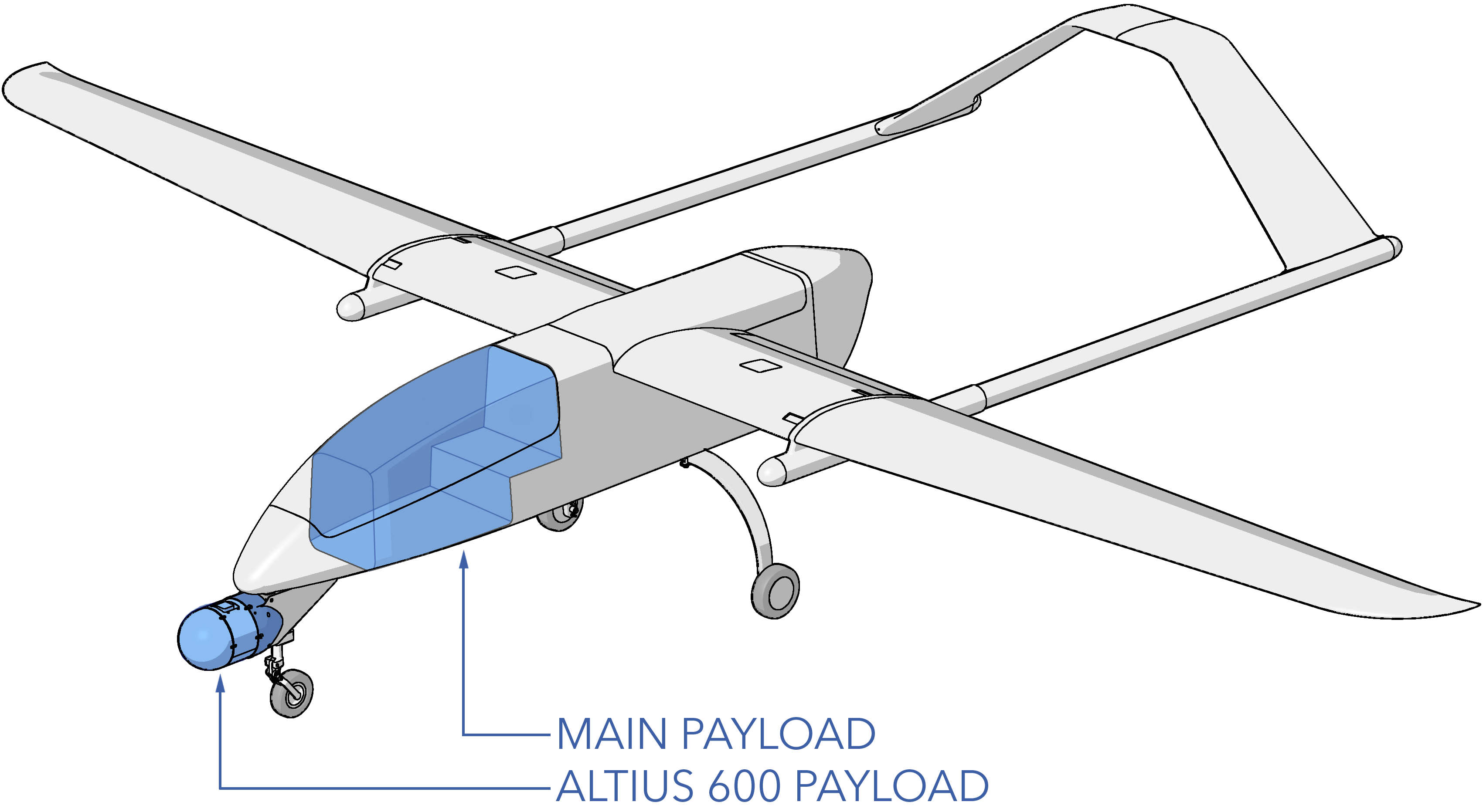
The Falcon Altius Surrogate mounts Altius 600 payloads on a chin mount under the nose, replicating the Altius fuselage and providing similar in-flight sensor visibility. This design offers better payload protection compared to belly-landing aircraft and extends the endurance available for payload testing thanks to the Falcon's endurance. Additional payloads are accommodated in the main payload bay, located under the fuselage canopy.
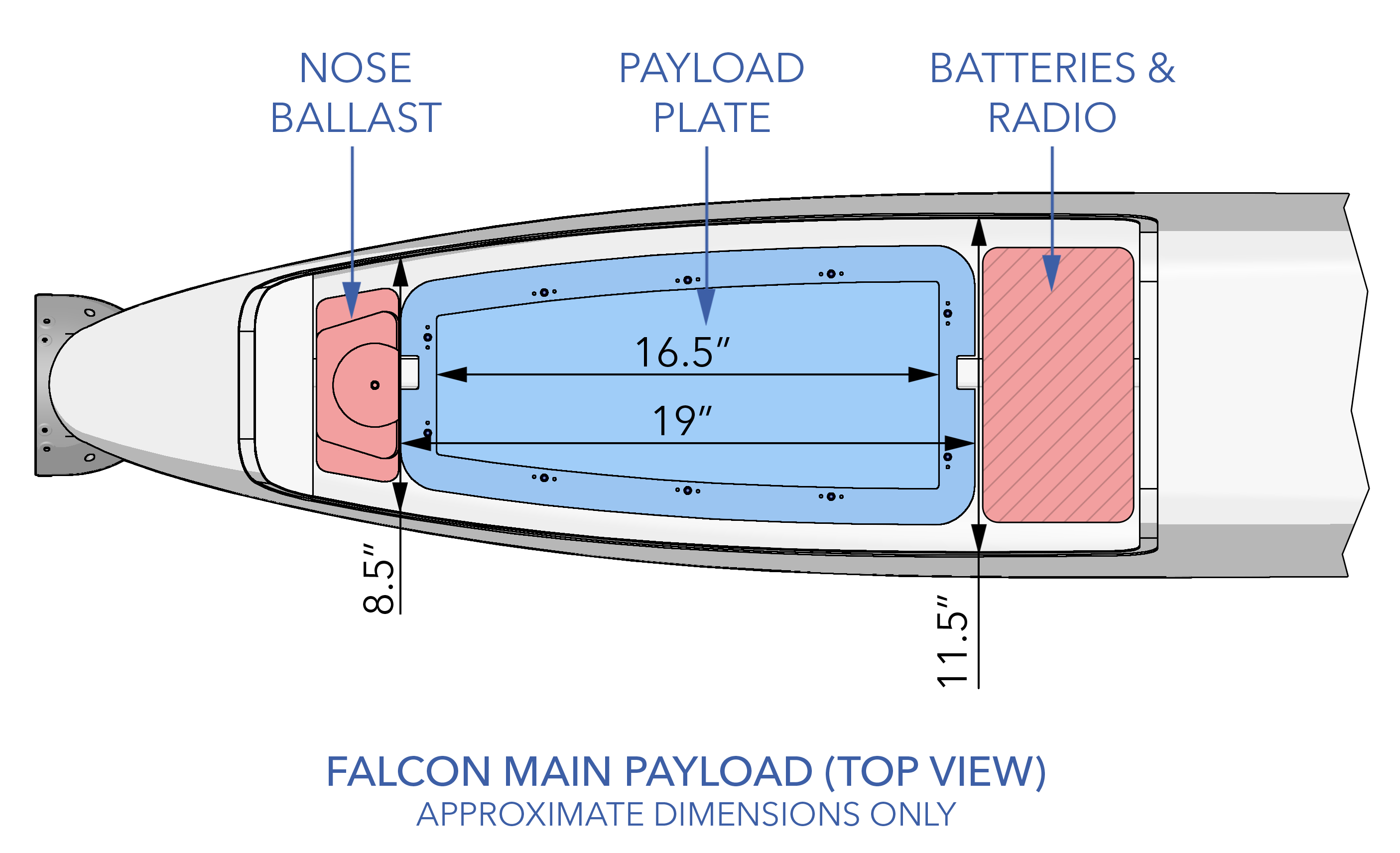
Main Payload
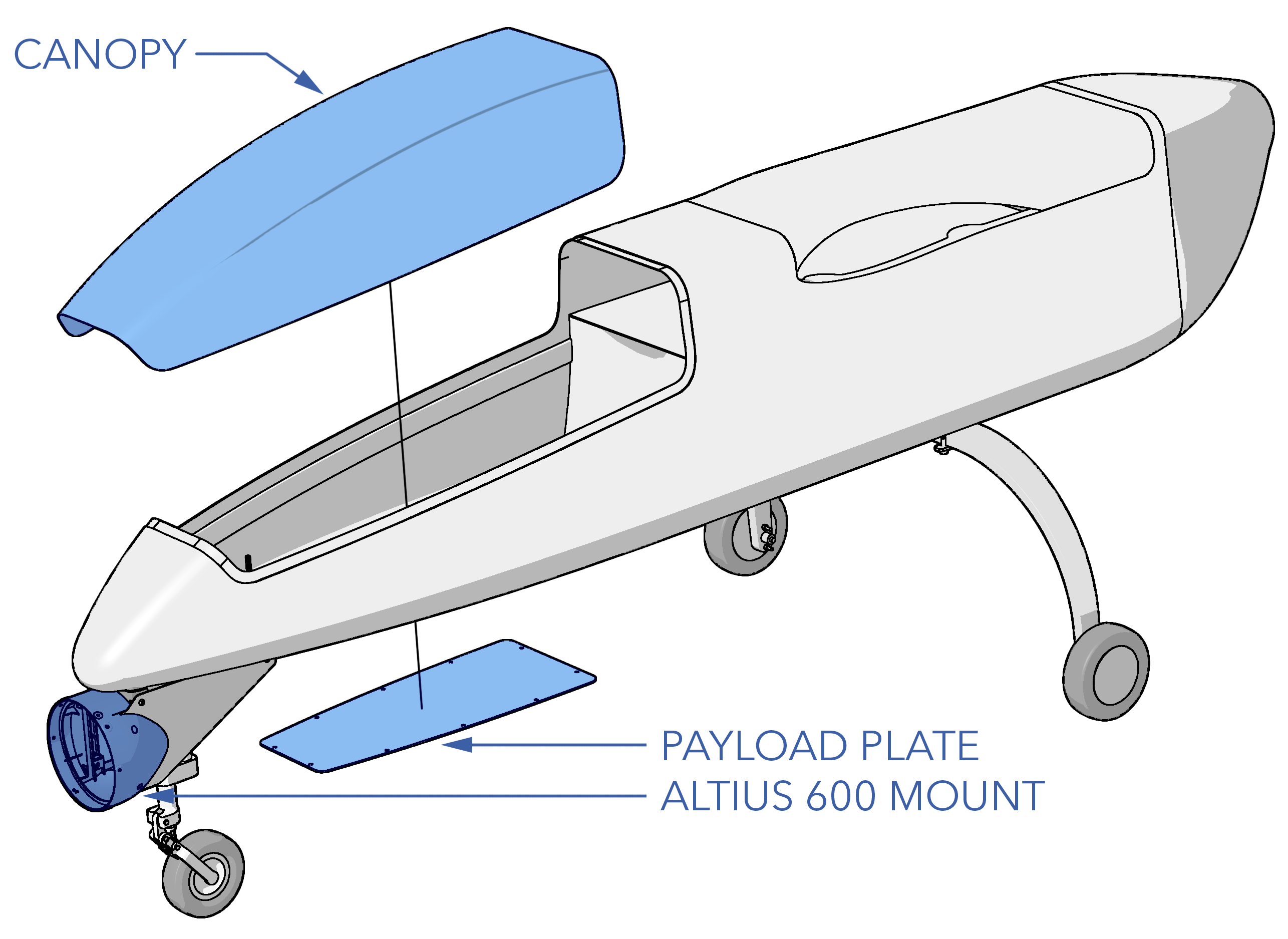
The main payload volume is approximately 1.53 cubic feet. This volume excludes the space occupied by the batteries, Silvus drop-in module, and main ballast. The lower section of the main payload bay is a removable payload plate. The plate can be removed for the installation and mounting of a payload or swapped out entirely to accommodate odd payload shapes, airflow requirements, or sensor cutouts. The payload plate mounts with 10x M4 x 10mm button head screws.
The upper section of the payload bay is bound by the aircraft canopy, which serves as the main access point to the fuselage during preflight. The canopy gives the OEM unobstructed access to the entire length of the payload bay for ease of integration. Similar to the bottom plate, the canopy itself can be modified to accommodate an even wider range of payloads. Mounting the canopy is achieve with a tab in the front and two quarter-turn fasteners.
Altius 600 Payload
The Altius 600 chin mount replicates the Altius 600 fuselage and shares the same flange diameter. Since an Altius payload partially forms the nose of the aircraft, extra effort must be taken by designers to reduce aerodynamic drag to allow for the best aircraft and payload performance. If the chin mount is not used, it is still recommended to install an empty payload fairing to reduce nose bluntness.
Mounting
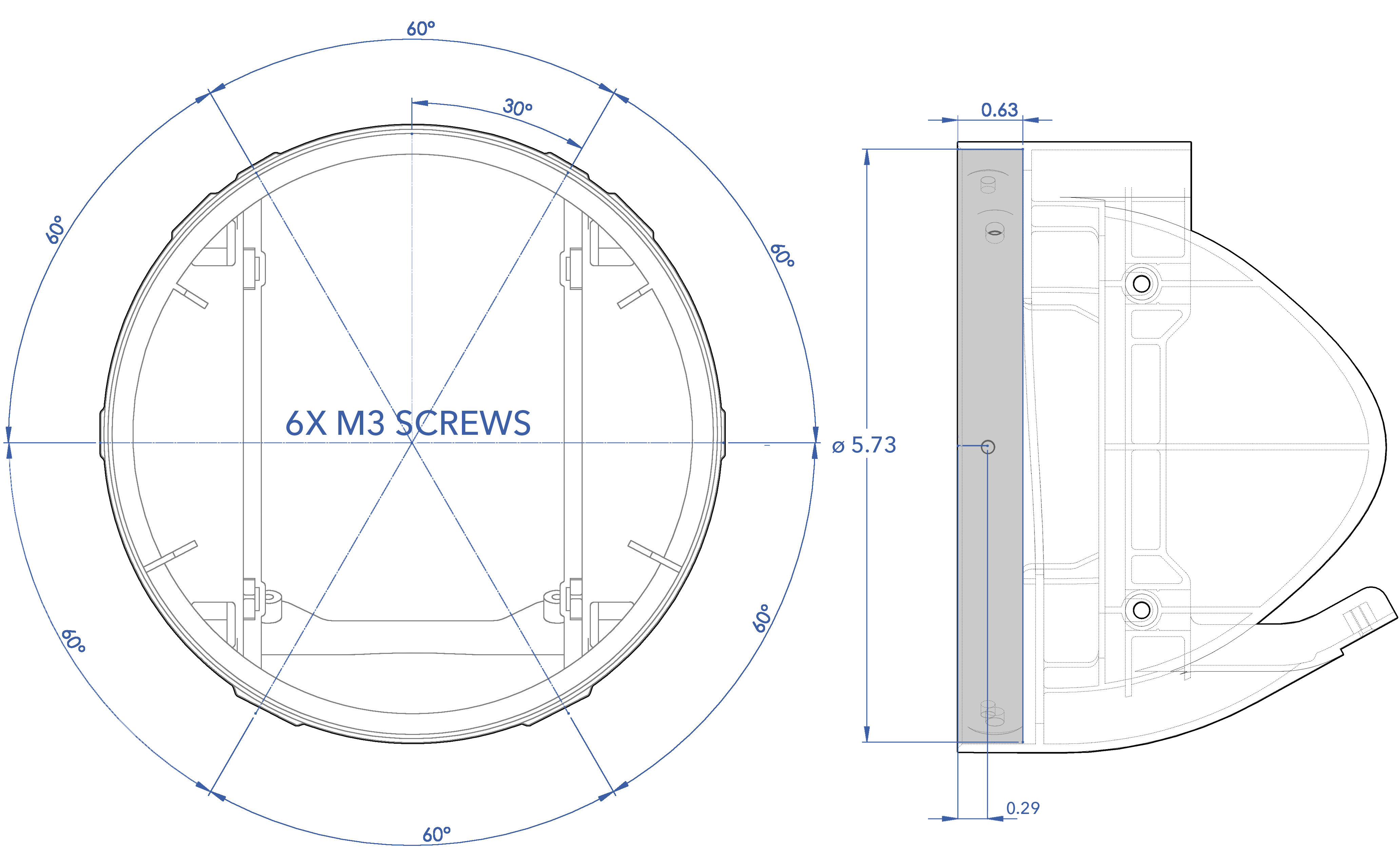
Mounting an Altius payload to the aircraft is achieved by inserting the payload into the chin mount and fastening with screws. The screws must match one of the two mounting patterns available. A chamfered flange is recommended, rather than a flat edge, to facilitate installation of the payload and, if necessary, compatibility with shims or spacers.
The first screw pattern (see below) is identical to the Altius 600. Mounting the payload to the aircraft is achieved by inserting the payload into the chin mount and fastening with 4x #8-32 button head screws. The minimum recommended screw length is 0.375”, depending on the payload's thread depth.
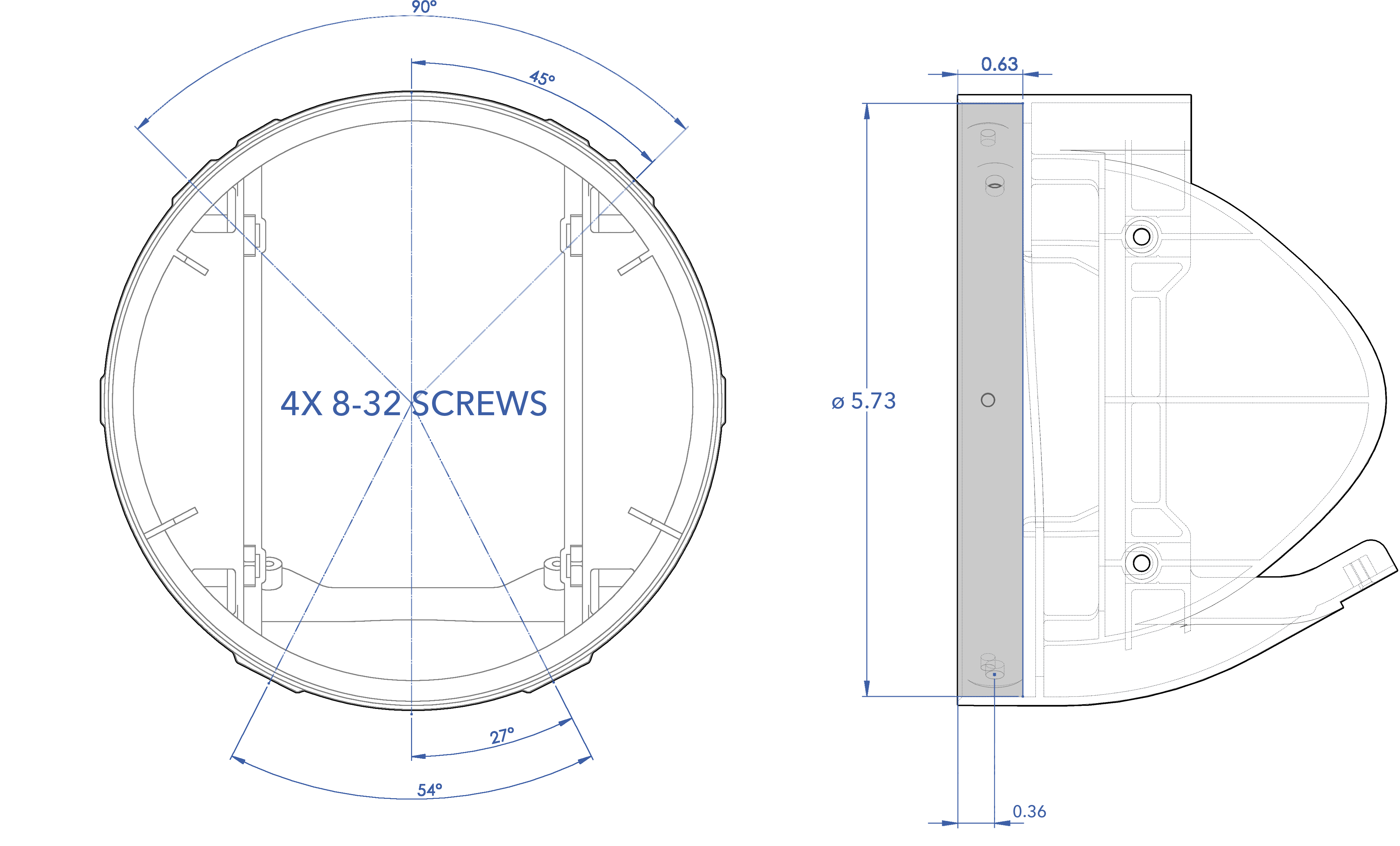
A second screw pattern (see below) accommodates other payloads, such as roll-mounted gimbal. A flange spacer may be required to match the 5.73" mating diameter. Payloads using this screw pattern are mounted using 6x M3 button head screws. The minimum recommended screw length is 10mm, depending on the payload's thread depth.
Weight and Balance
Proper weight and balance are critical for safe flight and optimal performance. The aircraft must remain within its center of gravity (CG) limits while not exceeding the maximum gross takeoff weight (MGTOW) of 180 lbs. Fuel and payload are the primary factors affecting weight and balance, but the Falcon’s CG-centric fuel tank minimizes fuel's impact on balance.
Adding or adjusting payload weight requires balancing the aircraft with ballast weight to stay within the CG limit. Ballast weight can be mounted in the nose or tail. Always include ballast weight when calculating MGTOW.
CG Location
For simplicity, Falcon has been designated one recommended CG location instead of a range. The Falcon CG is located 8.125" behind the leading edge (LE) of the center wing and is marked on the underside of each tail boom. This corresponds to roughly 40% of the mean aerodynamic chord (MAC).
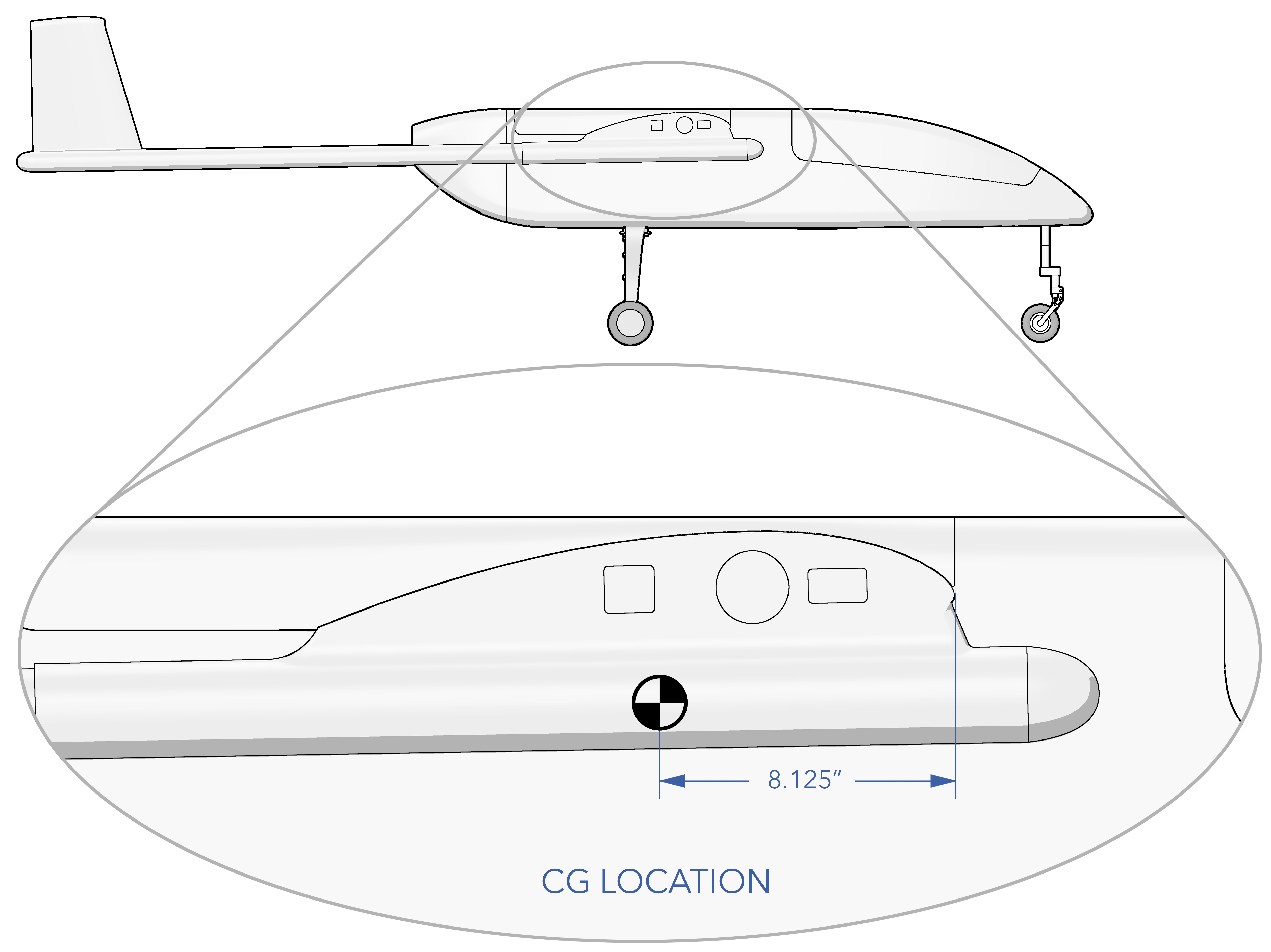
Only longitudinal CG is represented, vertical CG placement is for illustrative purposes only.
Payload integrators should design for a light, efficient configuration to maximize aircraft endurance and performance.
Weight and Balance Specs
| Parameter | Specification |
|---|---|
| Empty Weight* | 97.7 lbs |
| Max Gross Takeoff Weight (MGTOW) | 180 lbs |
| Max Payload Weight | 20 lbs |
| Max Fuel Weight | 63 lbs |
| CG Location & Datum | -8.125” from center wing LE |
| CG %MAC | 40% |
*For the purpose of the Altius Surrogate Falcon Appendix, the empty weight includes the payload battery, avionics battery, Silvus drop-in module, blade antennas, payload board, Altius 600 mount. It does not include payload or fuel.
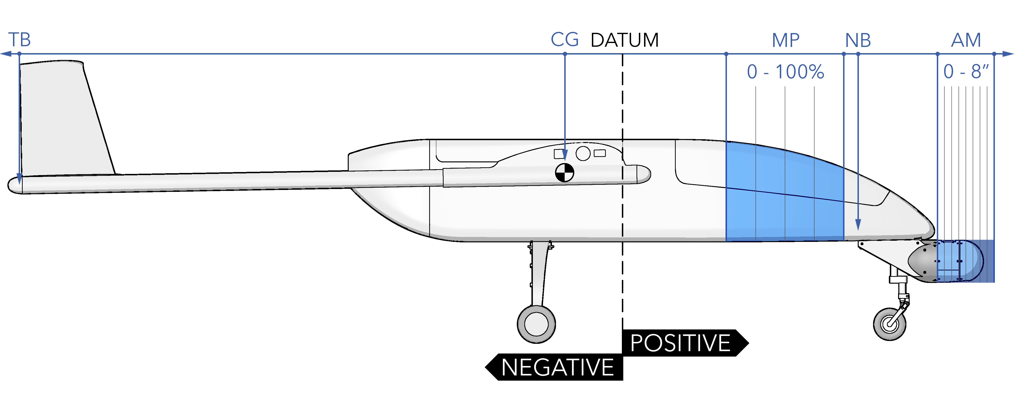
Mounting Locations
Key mounting locations are defined with respect to the aircraft's reference datum. The locations of the main payload (MP 0 - 100%), nose ballast (NB), Altius 600 mount (AM 0 – 8”), datum, aircraft center of gravity (CG), and tail ballast (TB) are illustrated below.
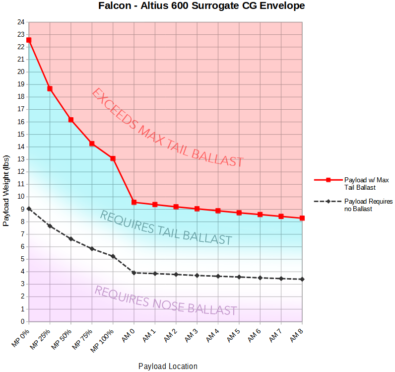
CG Envelope
The graph below shows allowable payload weights at different mounting locations, assuming the payload's center of mass is at the specified position. Use this as a reference for a single payload; for multiple payloads, refer to the CG Calculator.
CG Calculator
The CG Calculator starts with a Falcon, configured as an Altius Surrogate, without payload or fuel. This starting configuration includes the following integrated into the aircraft:
- Avionics and payload battery
- Silvus drop-in module and blade antennas
- Payload board
- Altius 600 mount
To use the Falcon calculator, select Add Item to Aircraft and choose the location that best represents the payload's center of mass, then input the weight. You may also choose Custom in the dropdown menu to input a unique moment arm if your desired payload location is not represented by one of the presets. Items added can be modified but not deleted. To delete or start over, select Reset.
The CG Envelope Graph and CG Calculator are for reference only. The aircraft balance with a new payload configuration must still be physically checked before flight.
| Location | Weight (lbs) | Arm (in) |
|---|
| Dry Weight | |
|---|---|
| Current CG | |
| Desired CG | |
| Add Ballast To: | |
| Required Ballast: | |
| Max Tail Ballast: | |
| Fuel Capacity: |
Vibration
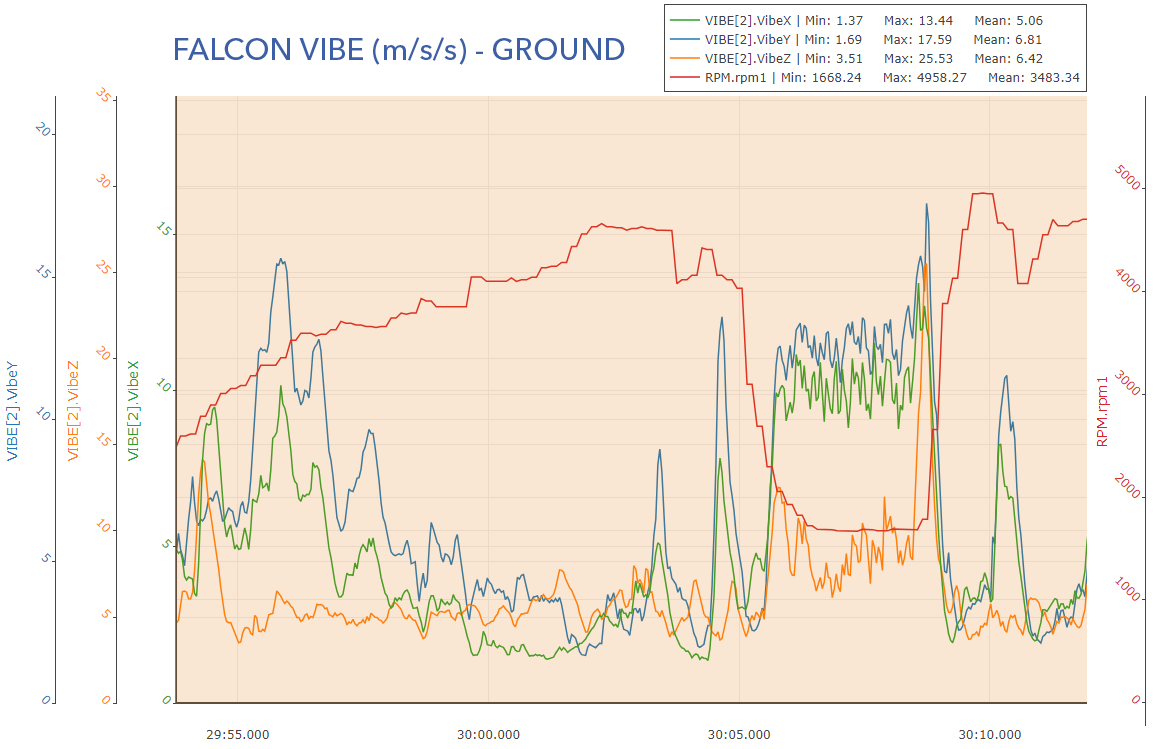
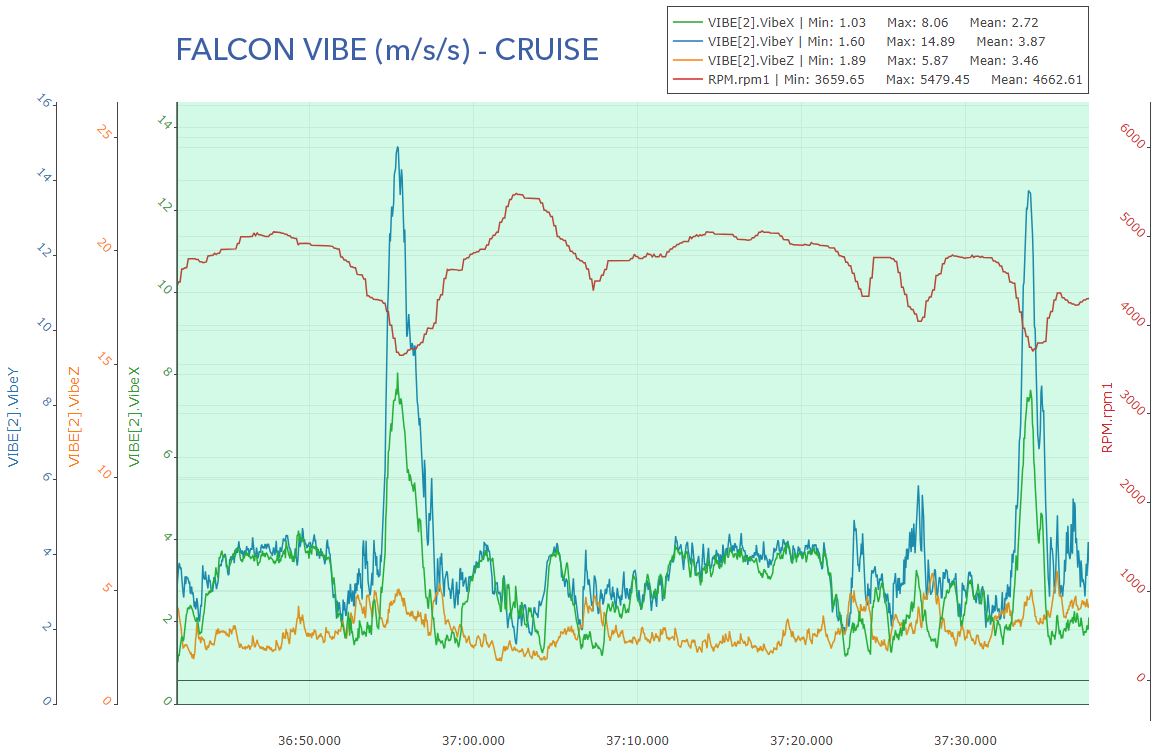
Payloads are mounted to the Falcon fuselage and therefore subject to in-flight vibrations and accelerations. Typical loads are up to 1.8 g laterally, 1.4 g longitudinally, and 2.6 g vertically. Vibrations are generally higher on the ground than in flight.
The vast majority of the vibrations are due to the reciprocating engine and thus there is a correlation between vibration and engine RPM. Low RPM, such as when idling, produces vibrations that are lower frequency but higher amplitude. At high RPM, vibrations occur at higher frequencies but with lower amplitudes.
Below are two vibration graphs of the Falcon. The first characterizes the aircraft on the ground with the engine running. The second is from an in-flight loiter.
- X Axis: aircraft forward and back, parallel to the fuselage
- Y Axis: aircraft left and right, parallel to the wing
- Z Axis: up and down
Environmental Requirements
It is recommended that the payload meets or exceeds the Aircraft Environmental Limits.
Electrical Interface Overview
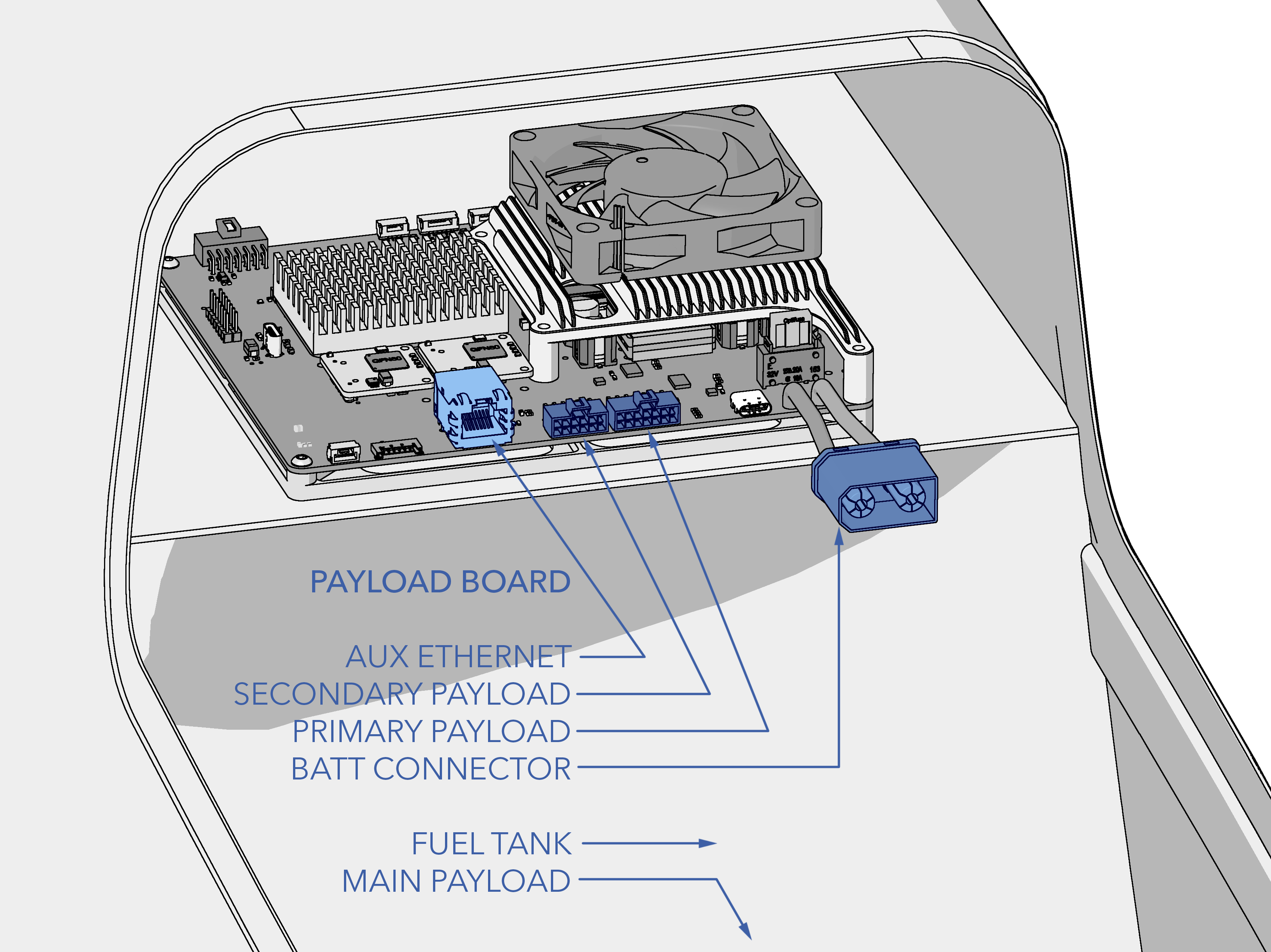
The Falcon Altius Surrogate utilizes the SpektreWork's Payload Board (PB). The PB is an interface module to enable the integration of payloads into low-cost aircraft that lack a native capability to power or interface with such payloads. It provides regulated power, power switching and monitoring, network connectivity, an optional single board computer, and serial ports. The PD itself is located behind the main payload bay, above the fuel tank.
The PB features a STM32F407 MCU running AudPilot’s AP_Periph firmware. AP_Periph leverages DroneCAN for reliable, real-time communications between the autopilot and peripheral devices.
The PB is equipped with a board-to-board connector interface designed for the Raspberry Pi Compute Module 4 (CM4). The CM4 primarily functions as a companion computer to the autopilot, routing MAVLink messages across multiple endpoints using MAVLink Router.
All GPIO pins are broken out to a 100 mil header for further feature expansion by the user.
Power
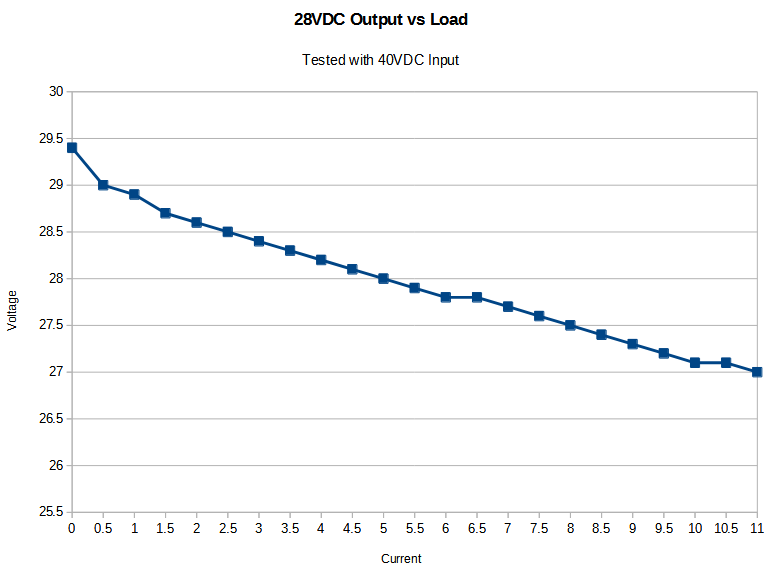
The PB can be powered from a 8S to 10S lithium ion battery and provides switchable 28V and 5V payload power. A separate 2S lithium polymer battery powers the avionics, actuators, and other critical aircraft components. Both batteries are located in the aft section of the main payload bay. The battery specifications can be found in the table below.
Battery Specs
| Parameter | Payload | Avionics |
|---|---|---|
| Type | Lithium Ion | Lithium Polymer |
| Quantity | 1 | 1 |
| Weight | 6.36 lbs | 1.92 lbs |
| Main Connector | QS8S | XT90 |
| Balance Connector | JST-XH | JST-XH |
| Voltage | 8S | 2S |
| Capacity | 25Ah | 23Ah |
| Fully Charged | 33.6V | 8.4V |
| Low Voltage | 24V | 7V |
| Critical Voltage | 20.8V | 6.6V |
| Charge Current | 12.5A (0.5C) | 11.5A (0.5C) |
| Heater | No | No |
| Service Lifespan | 500 cycles | 200 cycles |
| Expiration Date | 5 years | 2 years |
Power Supply
The voltage output on the 28VDC rail is load dependent. The graph below characterizes the typical output voltage given a current draw.
Communications
Both Ethernet and serial are available for payloads. The PB utilizes a single CAN bus as the primary interface between the PB AP_Periph node and the flight controller. Note, the CAN bus is currently reserved for internal use only.
Serial
There are four available serial interfaces for payloads. One provides a direct 3.3V UART passthrough to the autopilot. The second and third interfaces are 3.3V UART connections to the PB AP_Periph node. The fourth serial interface is connected to the aircraft's GPS secondary serial port. The aircraft may need to be reconfigured for the fourth serial interface to work properly.
Ethernet
The PB has five 10/100BASE-TX unmanaged ethernet ports, three of which are available to the user. The remaining two ports are dedicated to the avionics and IP radio. The default IP addresses are found in the table below:
| Equipment | IP Address | URL |
|---|---|---|
| Main Telemetry (RPI CM4) | 192.168.xxx.85 | computer-yyy.local |
| Secondary Telemetry (Lantronix) | 192.168.xxx.92 | primary-yyy.local |
| Air Radio (Silvus) | 192.168.xxx.87 | silvus-yyy.local |
- xxx - Unique aircraft ID provided by SpektreWorks
- yyy - Aircraft tail number
CAN Bus
UAVCAN protocol provides low-latency and reliable communication between the PB AP_Periph node and autopilot.
AP Periph Node
The AP_Periph node handles the power switching and monitoring and the serial-to-CAN bridge functionality of the PB.
Voltage monitoring is available for the following:
- Input voltage rail
- 28V and 5V power supply output voltage
- 28V and 5V switchable output voltage
MAVLink Router
The Raspberry Pi Compute Module 4 (CM4) operates a headless version of Ubuntu 24.04.1. The CM4 runs MAVLink Router, which is an application to distribute MAVLink messages between multiple endpoints (connections), depending on the target address. Connections can be made via UART, UDP or TCP. The application listens on six open UDP ports (14550-14555) allowing up to six GCS connections to the aircraft simultaneously. This allows the operator and other personnel to each have their own connection to the aircraft in flight. These simultaneous connections also greatly simplify handoff procedures for remote and split operations.
Connector Specs
| Primary Payload | Secondary Payload | Aux Ethernet | |
|---|---|---|---|
| Function | Payload Interface | Payload Interface | Payload Ethernet |
| Designation | J16 | J15 | J14 |
| Connector | Nano-Fit 14 pin | Nano-Fit 14 pin | RJ45 Jack |
| Part # | Molex 1053101214 | Molex 1053141212 | Molex 0934628320 |
| Mating Part # | Molex 1053081214 | Molex 1053081212 | RJ45 Plug |
| Power Control | Switchable | Switchable | - |
| Voltage Output | 28V (200W), 5V (2.5W) | 28V (42W) | - |
| Max Power (Fused) | 28V at 8A (225W), 5V at 1A (5W) | 28V at 2A (56W) | - |
| UART (3.3V) | Autopilot, AP_Periph | AP_Periph, Secondary GPS | - |
| Ethernet | - | - | 10/100BASE-TX 100 Mbps |
Pinouts
The pinouts for each of the PB payload connectors can be found in the tables below. Note, the I/O column is from the PB’s point of view.
Primary Payload
| Pin | Description | Notes |
|---|---|---|
| 1 | +28V | 28V Switchable |
| 2 | +28V | 28V Switchable |
| 3 | +5V | 5V Switchable |
| 4 | ETH1_RX_N | Ethernet IO |
| 5 | ETH1_RX_P | Ethernet IO |
| 6 | ETH1_TX_N | Ethernet IO |
| 7 | ETH1_TX_P | Ethernet IO |
| 8 | GND | Ground |
| 9 | GND | Ground |
| 10 | PPS | PPS Output |
| 11 | Autopilot UART 4 TX | Serial out (3.3V) passthrough to autopilot |
| 12 | Autopilot UART 4 RX | Serial in (3.3V) passthrough to autopilot |
| 13 | MCU_TX1 | Serial out (3.3V) from PB AP_Periph |
| 14 | MCU_RX1 | Serial in (3.3V) to PB AP_Periph |
Secondary Payload
| Pin | Description | Notes |
|---|---|---|
| 1 | +28V | 28V Switchable |
| 2 | +28V | 28V Switchable |
| 3 | ETH2_RX_N | Ethernet IO |
| 4 | ETH2_RX_P | Ethernet IO |
| 5 | ETH2_TX_N | Ethernet IO |
| 6 | ETH2_TX_P | Ethernet IO |
| 7 | GND | Ground |
| 8 | GND | Ground |
| 9 | MCU_TX3 | Serial out (3.3V) from PB AP_Periph |
| 10 | MCU_RX3 | Serial in (3.3V) to PB AP_Periph |
| 11 | GPS_UART2_TX | Serial out (3.3V) passthrough to Secondary GPS |
| 12 | GPS_UART2_RX | Serial in (3.3V) passthrough to Secondary GPS |
Aux Ethernet
| Pin | Description | Notes |
|---|---|---|
| 1 | ETH_P3B_A_P | Ethernet IO |
| 2 | ETH_P3B_A_N | Ethernet IO |
| 3 | ETH_P3B_B_P | Ethernet IO |
| 4 | N/C | |
| 5 | N/C | |
| 6 | ETH_P3B_B_N | Ethernet IO |
| 7 | N/C | |
| 8 | N/C |