Preflight Checklist
Always adhere to the Falcon Performance and System Limitations.
Adherence to the preflight checklist is crucial to the safe and successful operation of the Falcon. The preflight steps must be performed before every flight. Failure to preform a preflight step can result in a total loss of the aircraft and pose a hazard to personnel on the ground.
If using an EFI engine, once powered it must be treated as a ‘hot’ system and exercise extreme caution. The startup has three layers of safety:
- Enabling Control Surfaces: Via the GCS.
- Arming the Vehicle: Via the GCS.
- Flip the Ignition Switch: Via the hand controller.
Contents
- Preflight Checklist
- Power Source - Ensure
- Ground Equipment - Assemble
- Aircraft - Assemble
- Aircraft - Inspect
- Pitot Tube - Extend
- Propeller - Torque
- Avionics Battery - Install
- Aircraft - Fuel
- Weight and Balance - Verify
- Telemetry Radio - Connect
- Hand Controller - On
- Avionics Battery - Connect
- Autopilot - Connect
- Firmware - Check
- Parameter Checks
- Old Mission - Clear
- Mission - Create
- Mission - Upload
- Flight Modes - Verify
- Failsafes - Verify
- Autopilot - Warmup
- Airspeed - Calibrate
- Compass - Check
- Mode - Manual
- Control Surfaces - Enable
- Manual Control - Check
- Mode - FBWA
- FBW Response - Check
- Mode - Manual
- Brakes - Test
- Hatches - Secure
- No Warnings - Verify
- Select Engine Type for Launch
Power Source - Ensure
Ensure that you have access to a power source that is capable of powering all necessary equipment throughout the entire duration of the flight.
This step applies to powering the ground support equipment. Common power sources include shore power and generators.
Ground Equipment - Assemble
Inspect and assemble the NOB, GCS, IP radio, and hand controller.
This list may change depending on your mission or aircraft configuration. At a minimum, this will include the GCS computer, IP radio, network operations box (NOB), and hand controller.
IP RADIO
- Set the NOB on a stable, level surface.
- Unlatch and remove the front and rear covers.
- Plug the Main NOB AC Power cable into an appropriate 120VAC outlet.
- Power on the SNOB by first pressing the main power button, followed by the enter button.
- Verify that the UPS has adequate battery for operations with a safety margin in the event of a power interruption. The NOB will charge the UPS batteries while plugged in.
- Connect the ground antennas to the radio. See the Antenna Tracker Appenix if using an antenna tracker.
- If powering the radio from the NOB, connect the battery eliminator to the radio and plug the opposite end into the NOB.
- If using battery power, connect the radio battery to the radio. Verify that the battery is sufficiently charged. A fully charged battery lasts approximately 12 hours.
- Connect the primary cable to the radio, and the opposite twist-lock end into the NOB.
- Power on the radio.
- Plug the GCS computer into an appropriate AC outlet.
- Connect the ethernet cable to the GCS, plug the other side into the NOB.
- Power on the GCS.
- Verify that the screen brightness is adequate for your working conditions.
- Verify that the GCS computer has adequate battery for operations with a safety margin in the event of a power interruption.
- Launch the Mission Planner software.
- Launch payload software if applicable.
- Connect the Hand Controller
- Inspect the switches and gimbals. The switches should freely move to each position. The gimbals should move without any resistance or grinding and, with the exception of throttle, should center when released.
- Set the throttle stick to idle (down) and the ignition switch to OFF. The flap switch should be set to flaps up.
- The hand controller is a power over ethernet (POE) device and is powered by the NOB. Connect the ethernet cable into the hand controller, and the opposite twist-lock end into the NOB.
- Power on the hand controller.
- Ensure the appropriate Falcon model is selected and displayed on the hand controller screen.
RFD900
- Plug the GCS computer into an appropriate AC outlet.
- Connect the telemetry data/power cable into the GCS
- Power on the GCS.
- Verify that the screen brightness is adequate for your working conditions.
- Verify that the GCS computer has adequate battery for operations with a safety margin in the event of a power interruption.
- Launch the Mission Planner software.
- Launch payload software if applicable.
- Inspect the switches and gimbals. The switches should freely move to each position. The gimbals should move without any resistance or grinding and, with the exception of throttle, should center when released.
- Set the throttle stick to idle (down) and the ignition switch to OFF. The flap switch should be set to flaps up.
- Connect the PPM input cable into the auxiliary port on the back of the Hand Controller.
- Power on the hand controller.
- Ensure the appropriate Falcon model is selected and displayed on the hand controller screen.
Fueler
- Fill the fueler with the appropriate gas/oil/treatment mixture and volume.
- Verify that the scale works.
- Connect the fueler to a power source.
Refer to the Fueling Section for detailed fueling and mixing instructions.
Aircraft - Assemble
Assemble the aircraft components.
Assembly of the aircraft requires a minimum of two people.
- Remove the aircraft components from the crate and place them in a clearing suitable for assembling the aircraft. An area measuring 20 x 20 feet (6 x 6 meters) is preferred.
- Remove the fuselage from the case and place it on the ground
- Place the Center Wing on a flat surface and insert the wing spars.
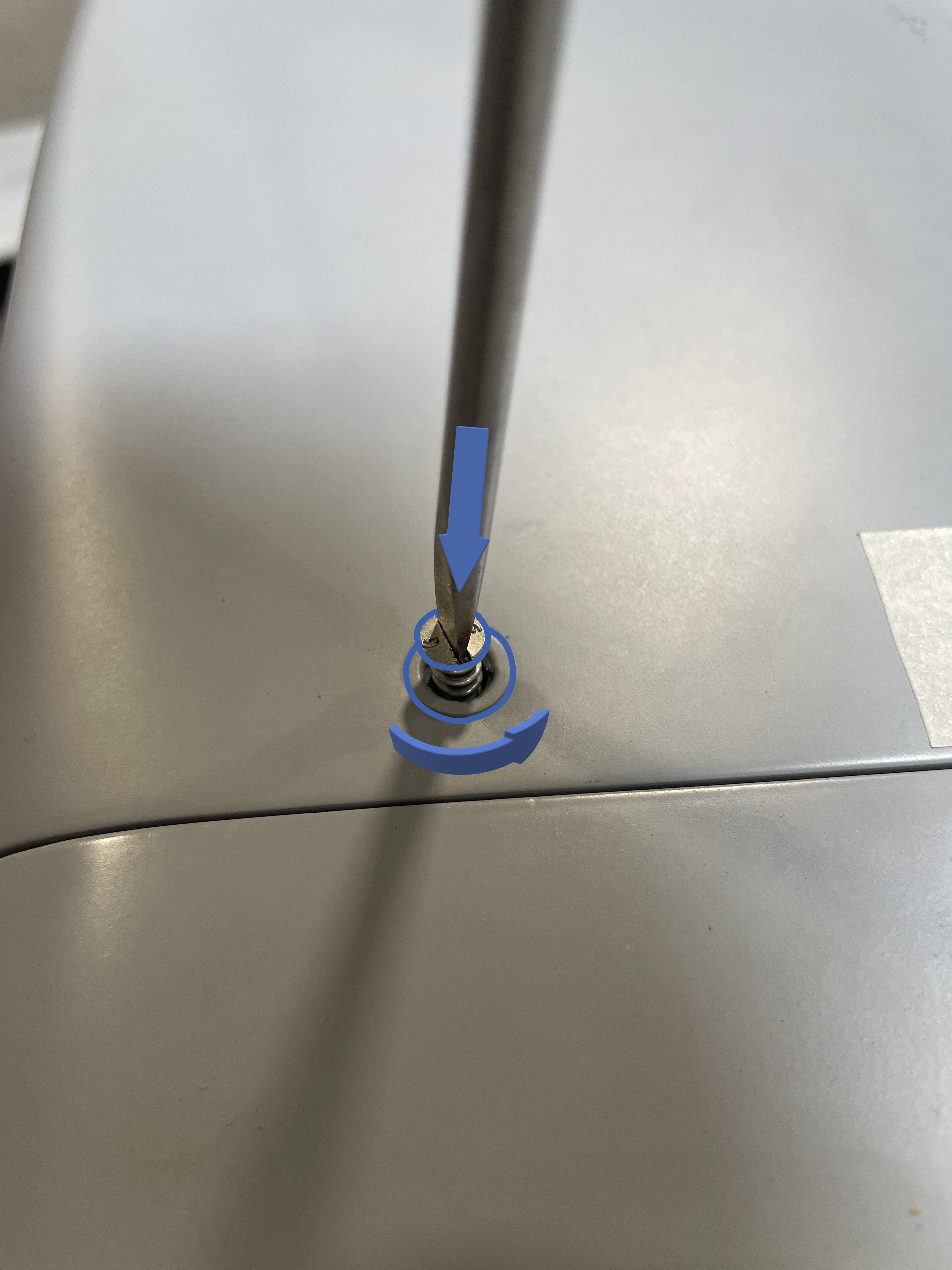
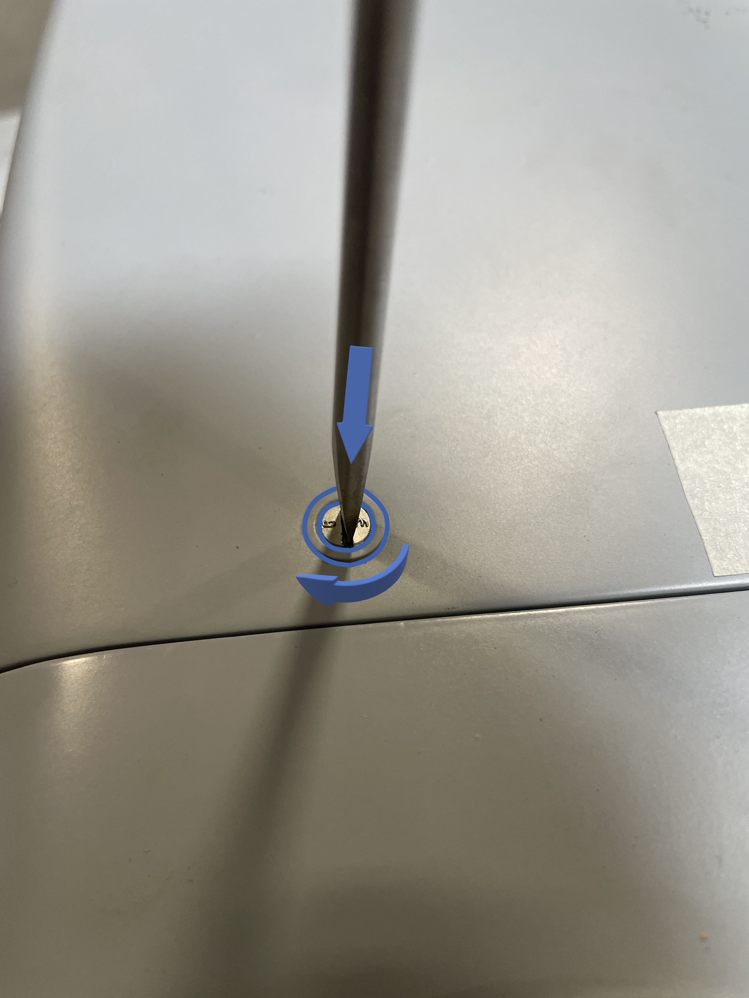
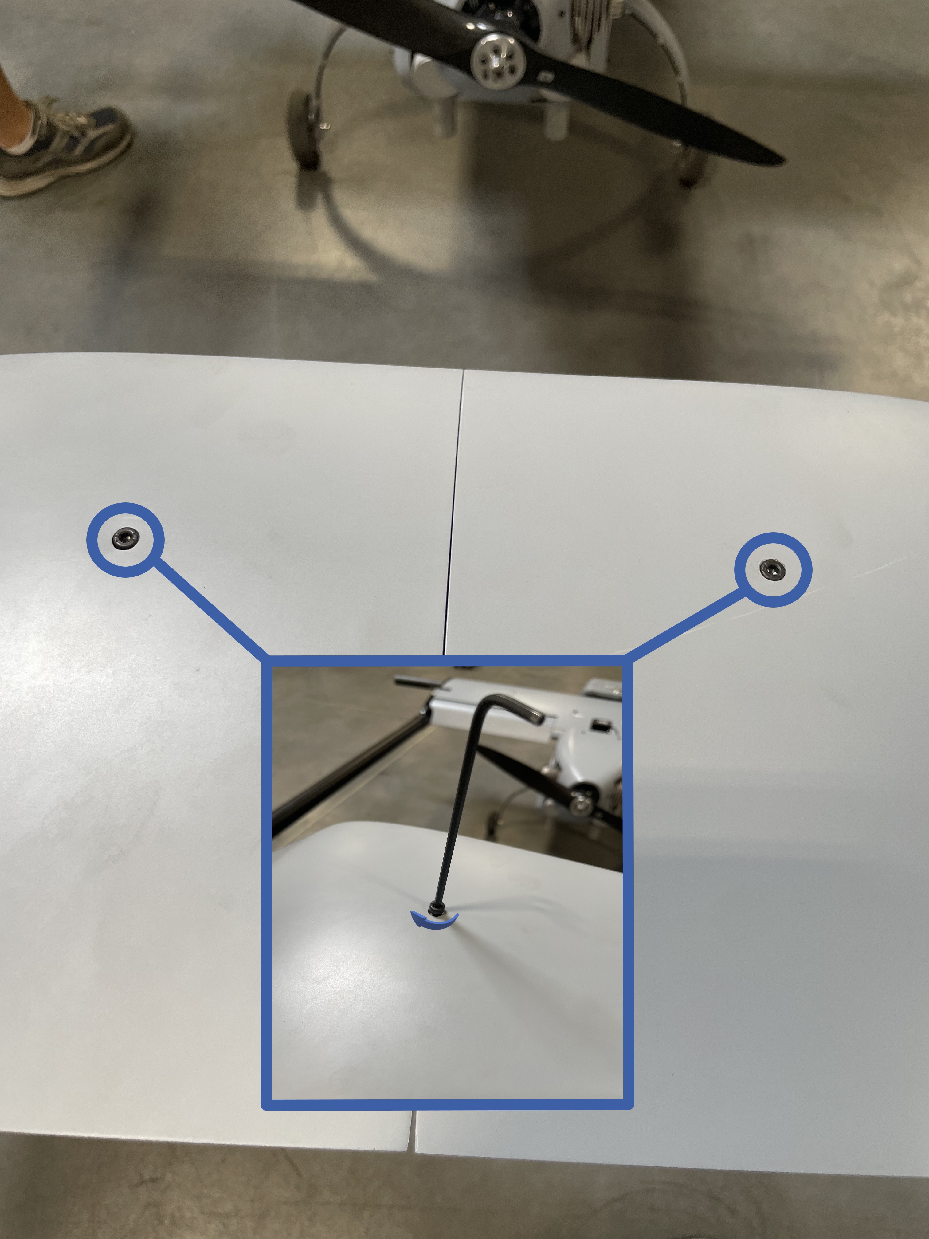
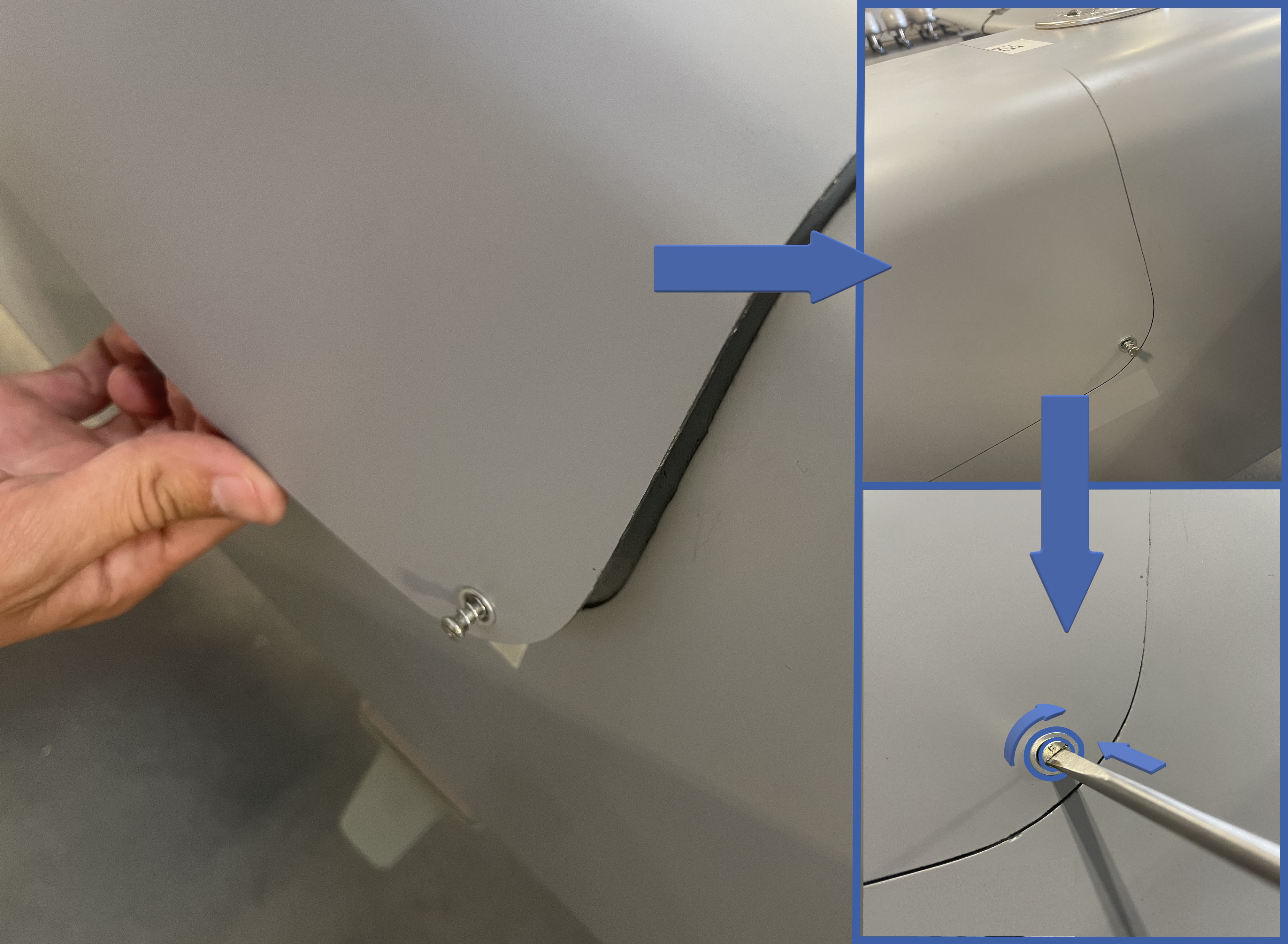
This aircraft utilizes 1/4 turn fasteners for both hatches, a flat head screw driver is required to fasten and unfasten these.
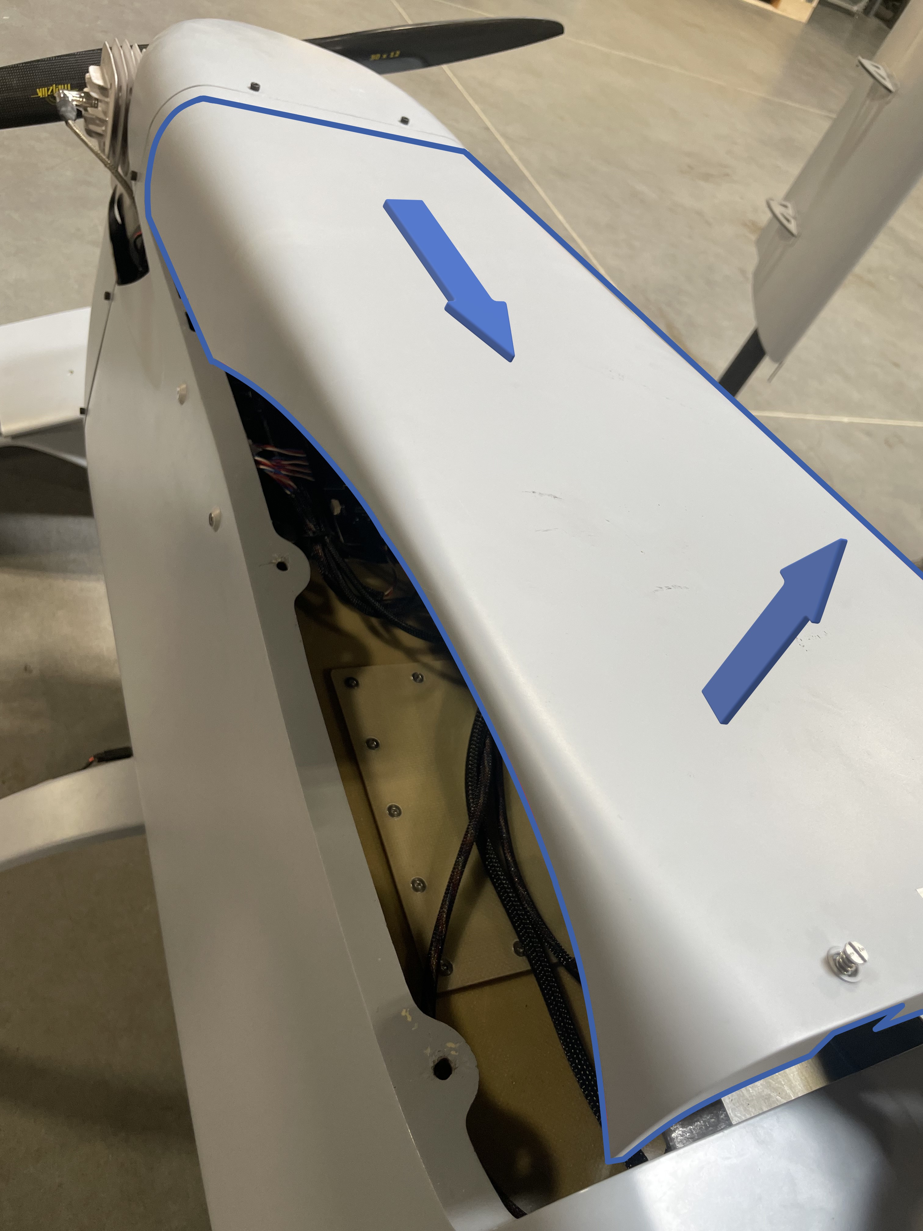
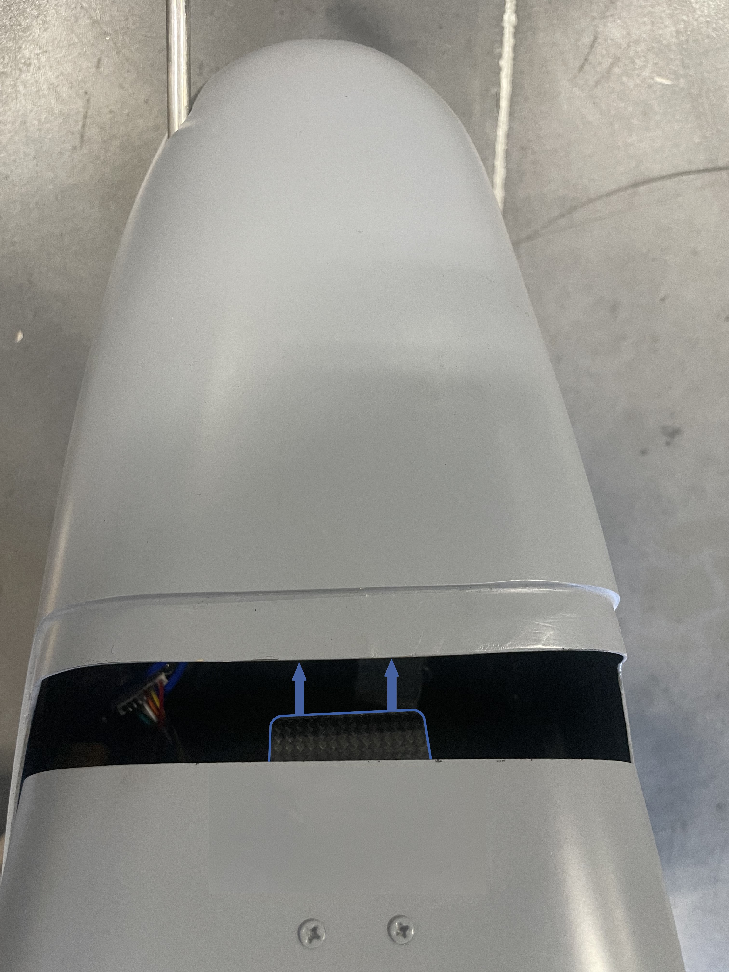
- Remove the wing cover from the fuselage.
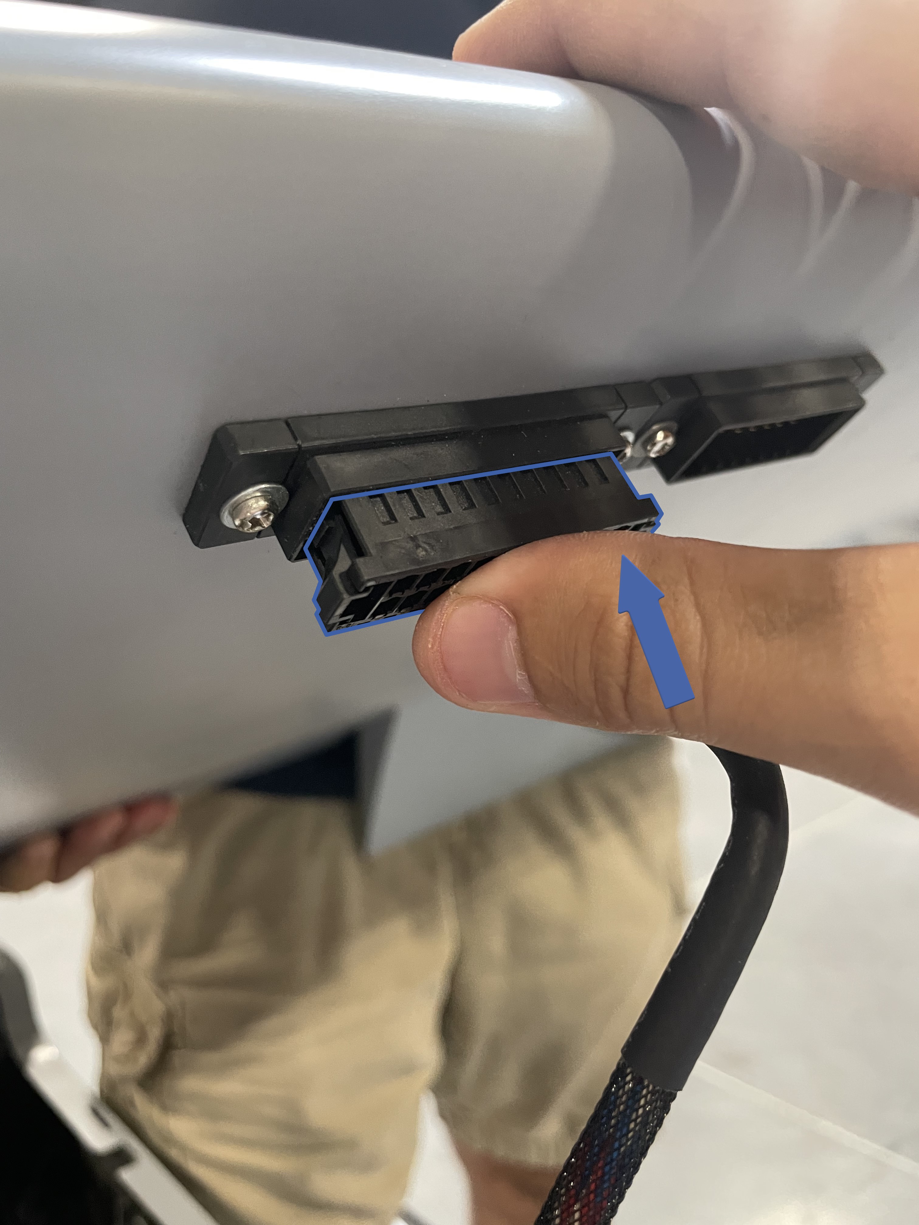
- While the Center Wing is being held above the fuselage, locate the connectors that will plug into the Center Wing. Press each connector into place until an audible "click" is heard.
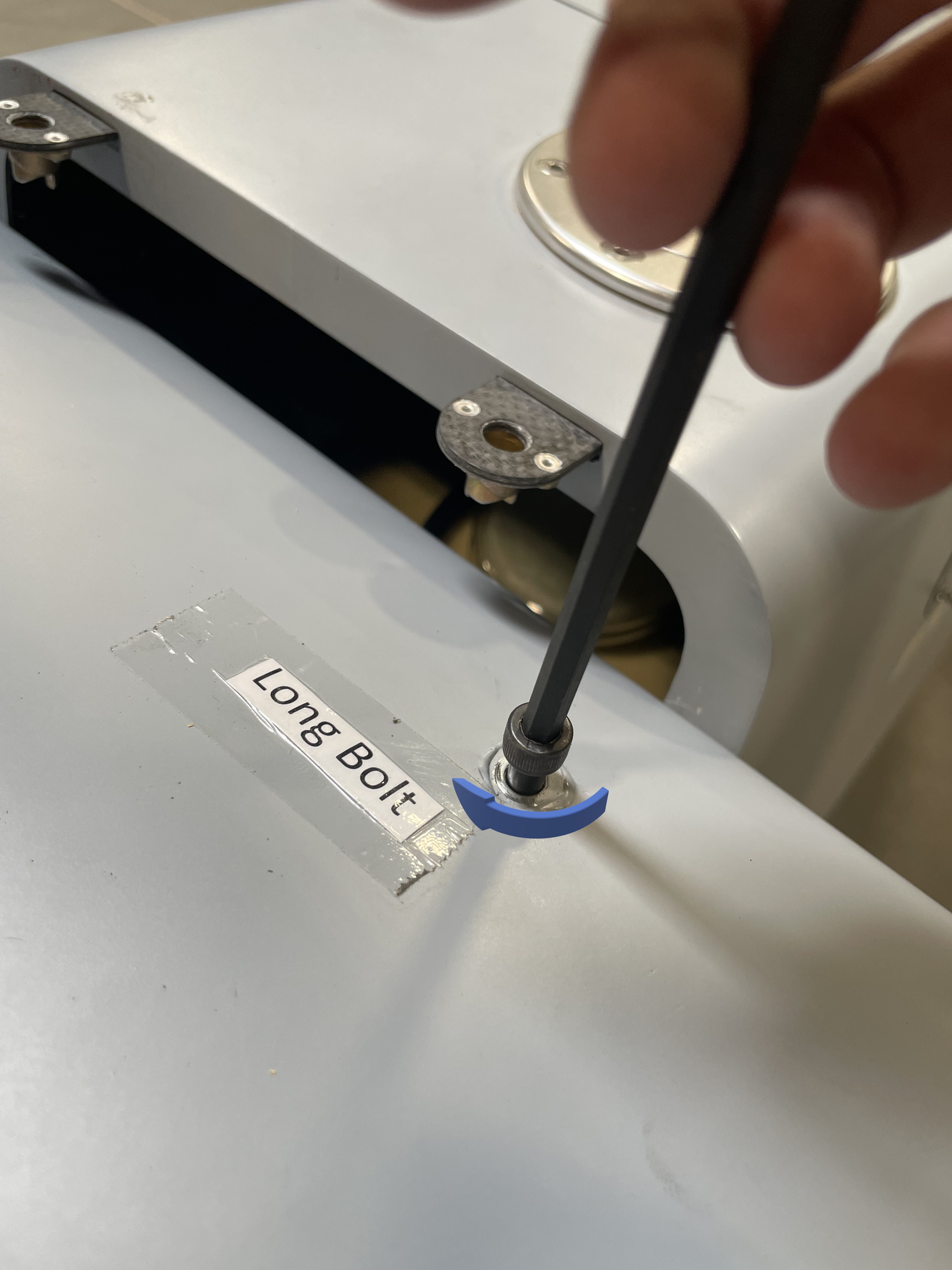
- Locate the center wing bolts, ensuring to use the long bolts on the front and short bolts in the rear.
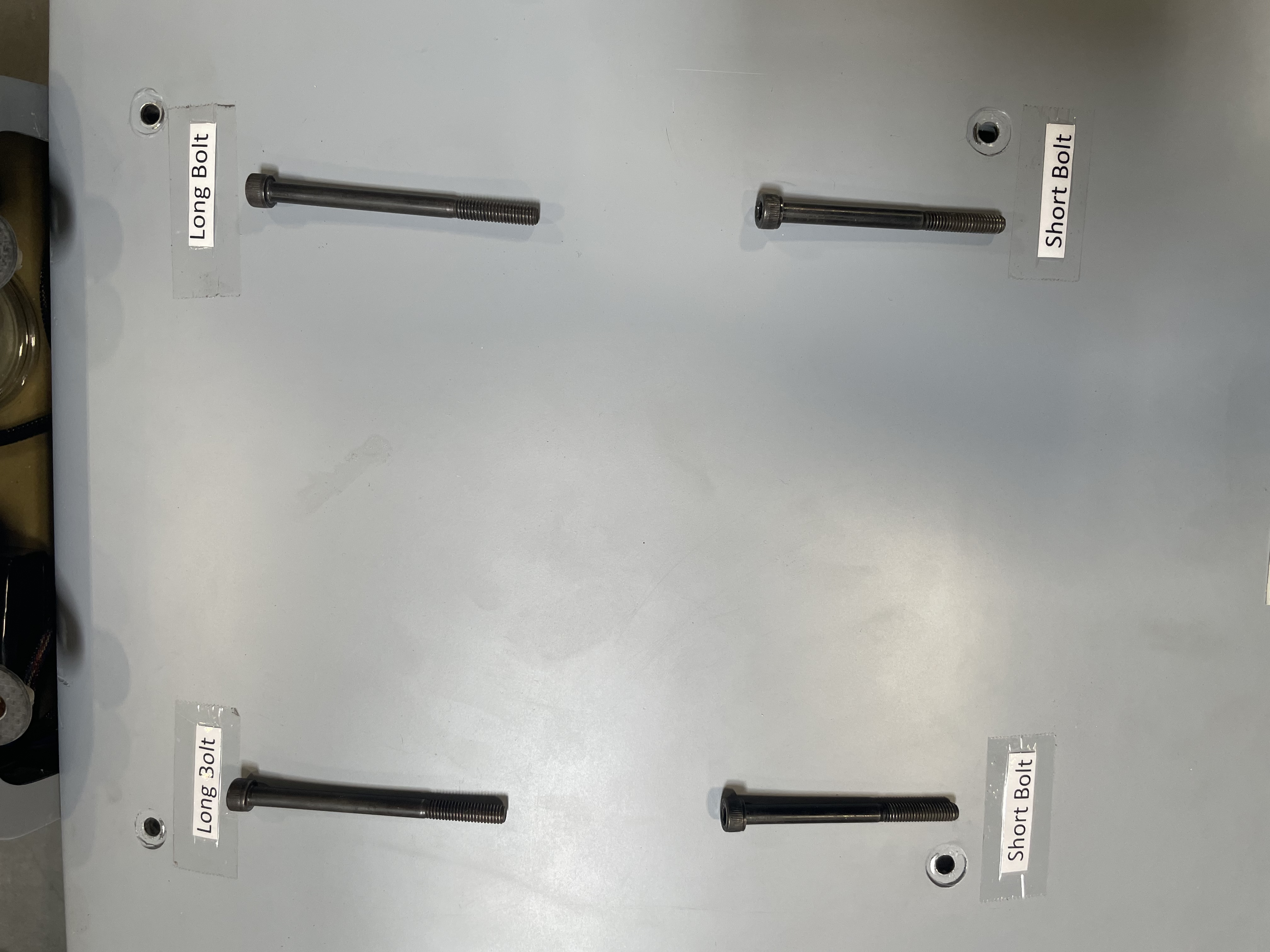
- Tighten each bolt until snug.
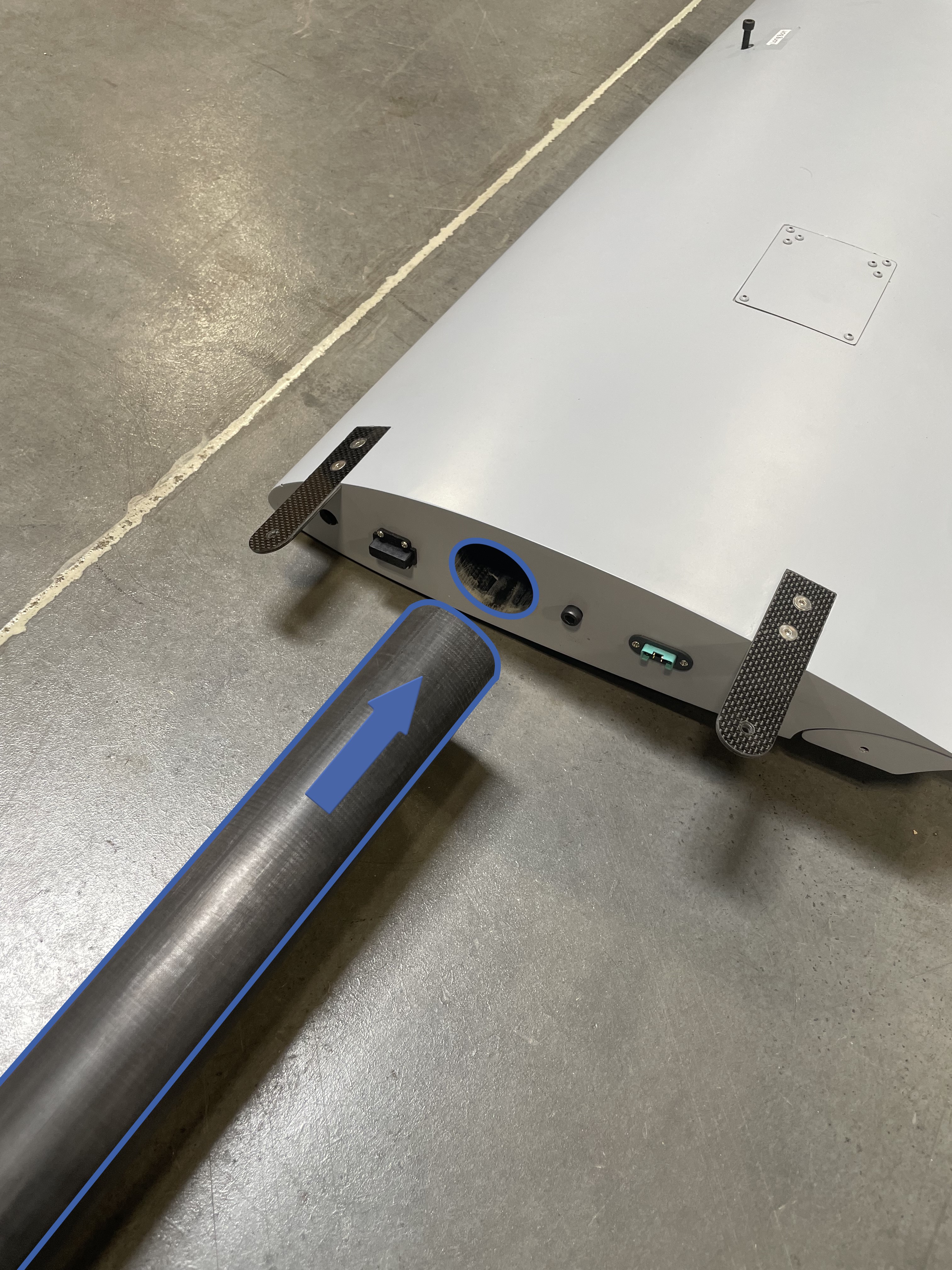
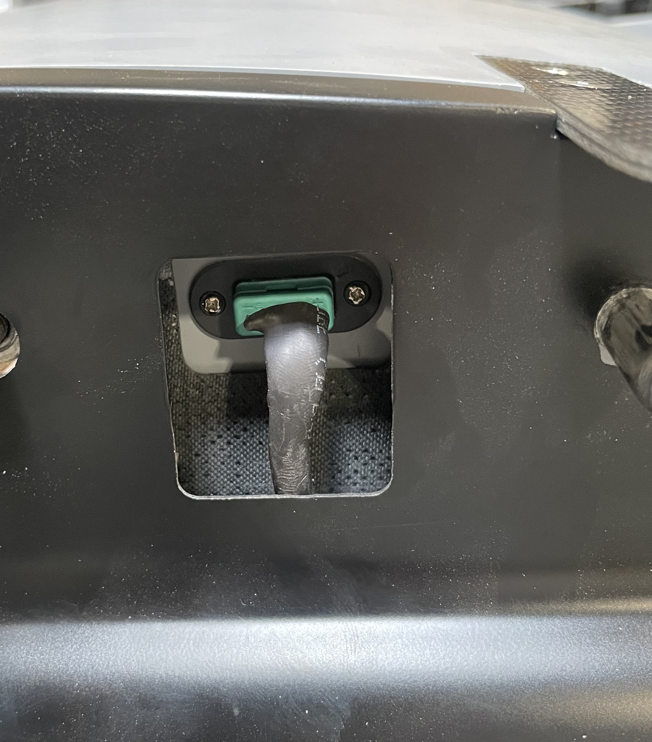
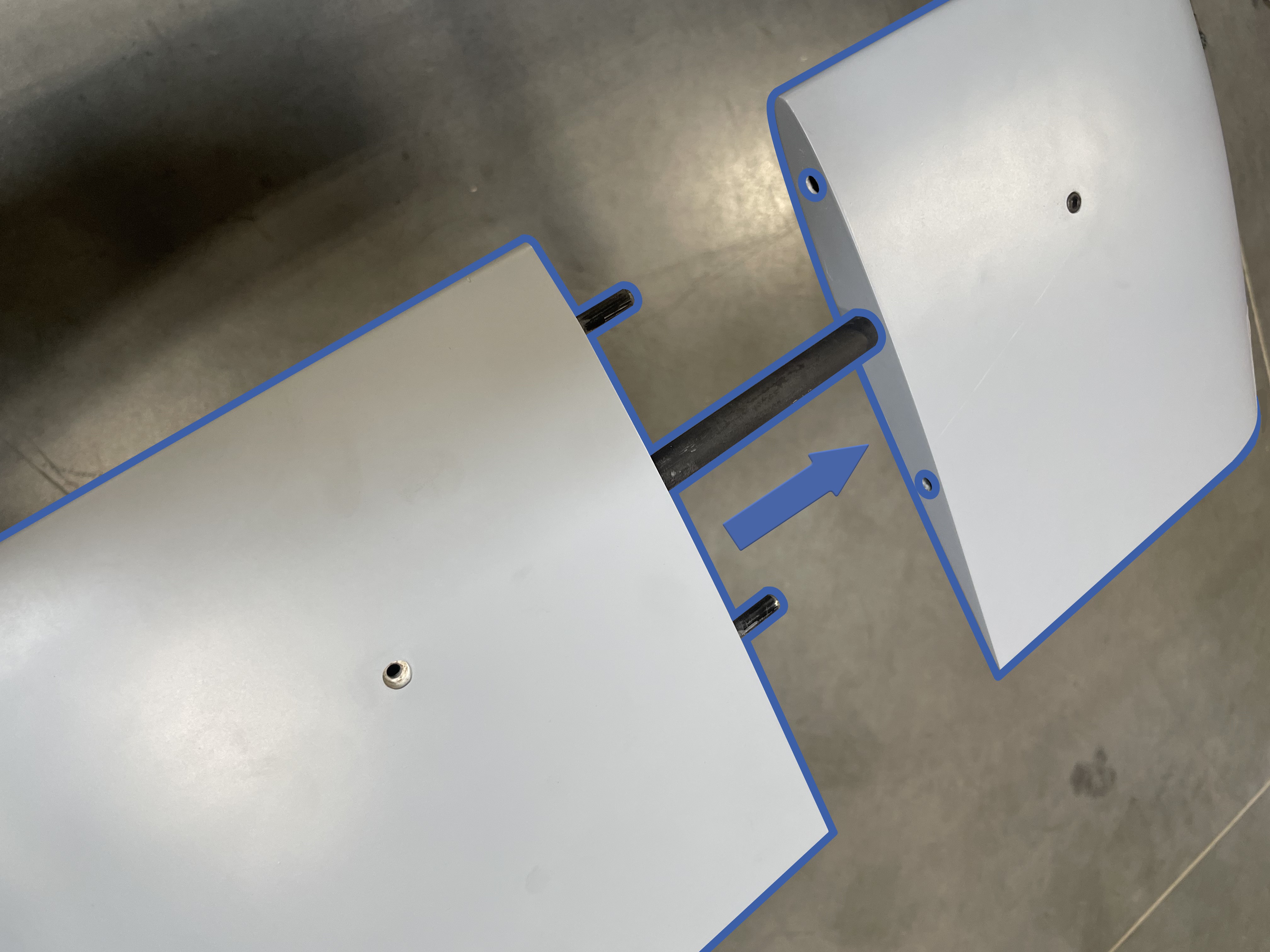
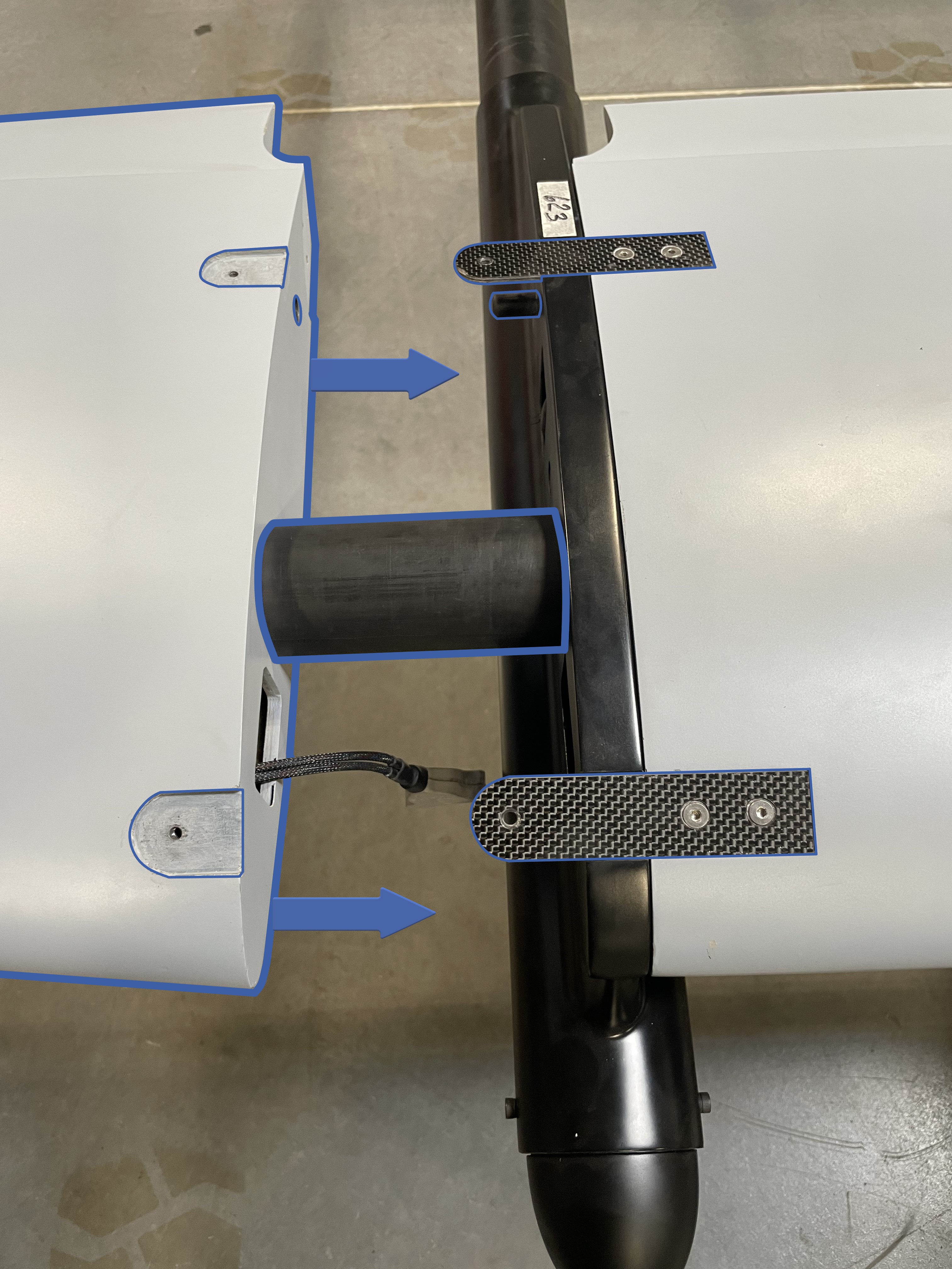
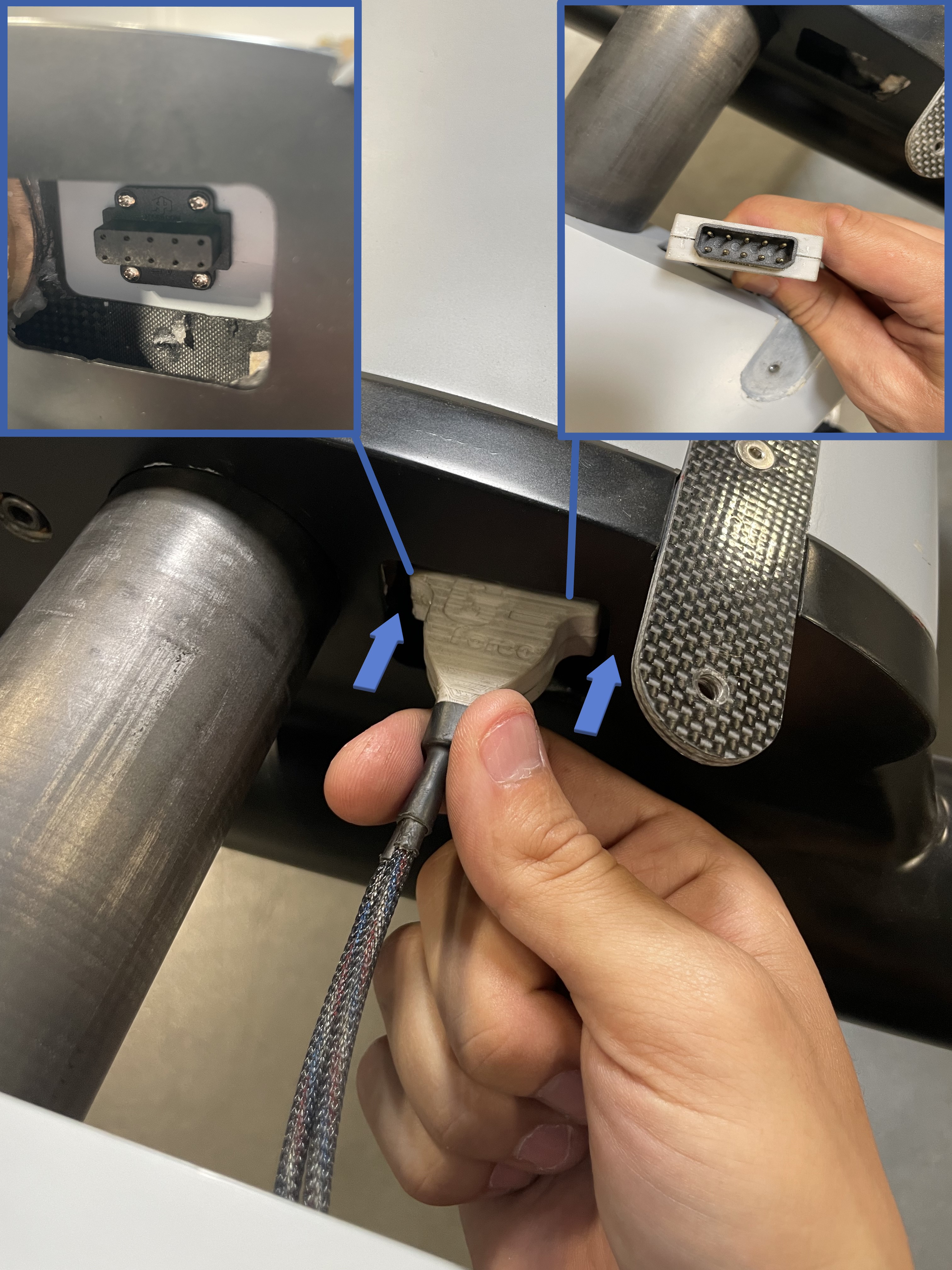
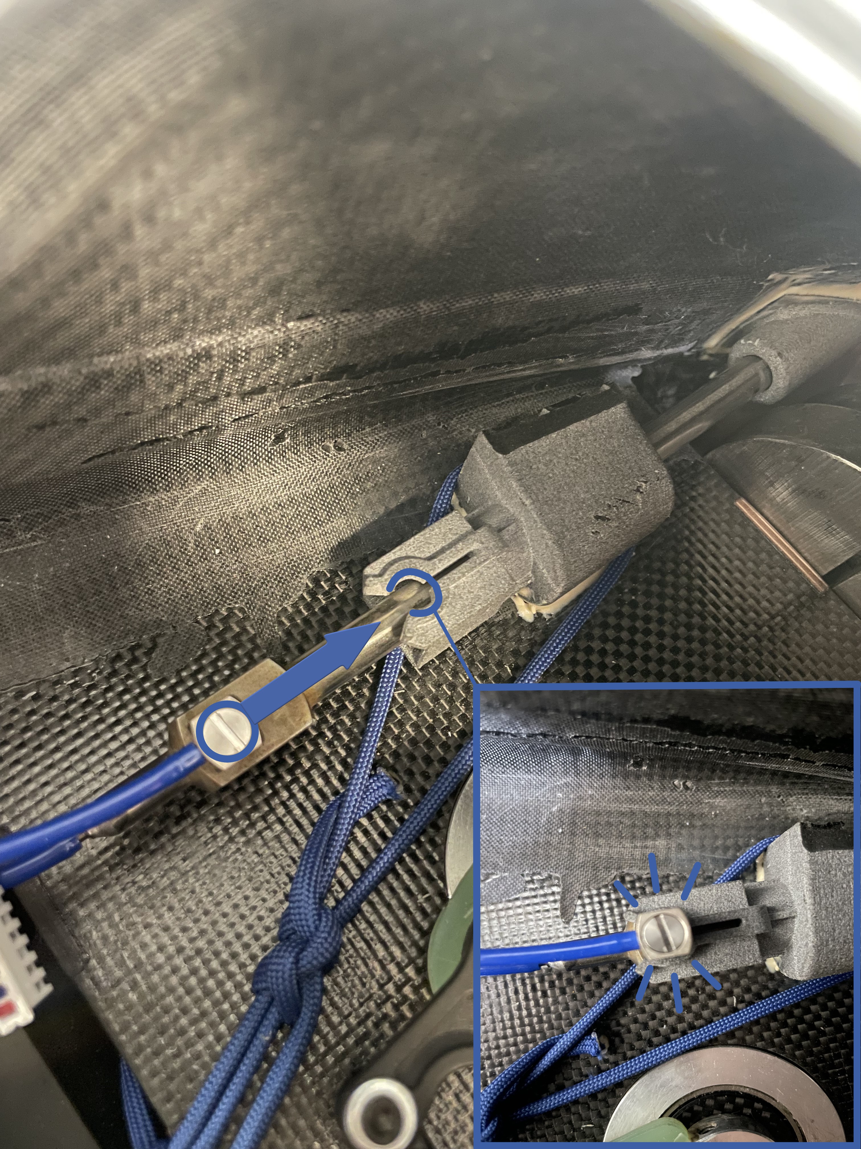
- Locate one of two boom sections and slide it onto the main wing spar.
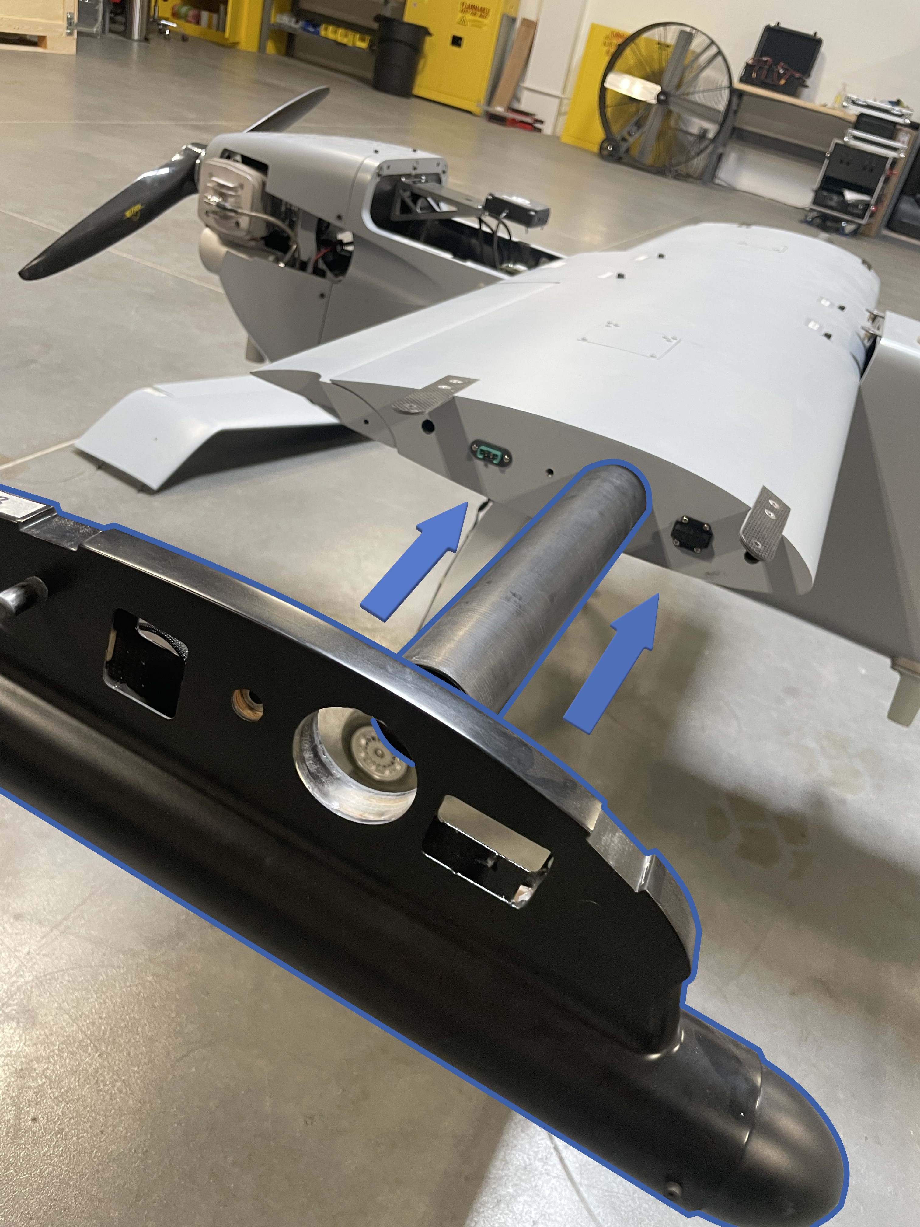
- Ensure that the green connector is inserted and seated into the green connector on the main wing.
This connector is keyed with a small rectangle on the bottom, it will only fit one way.
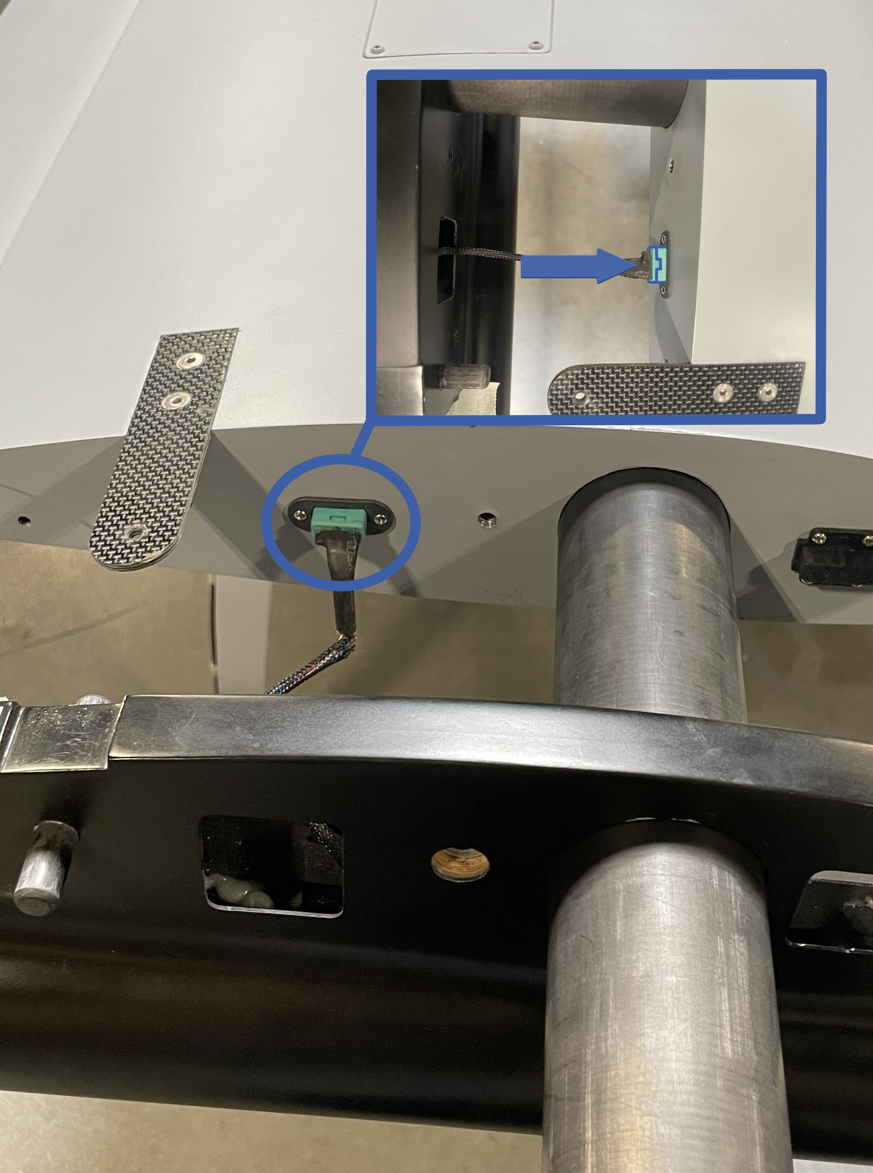
- Tuck any remaining length of the wire into the boom cavity.
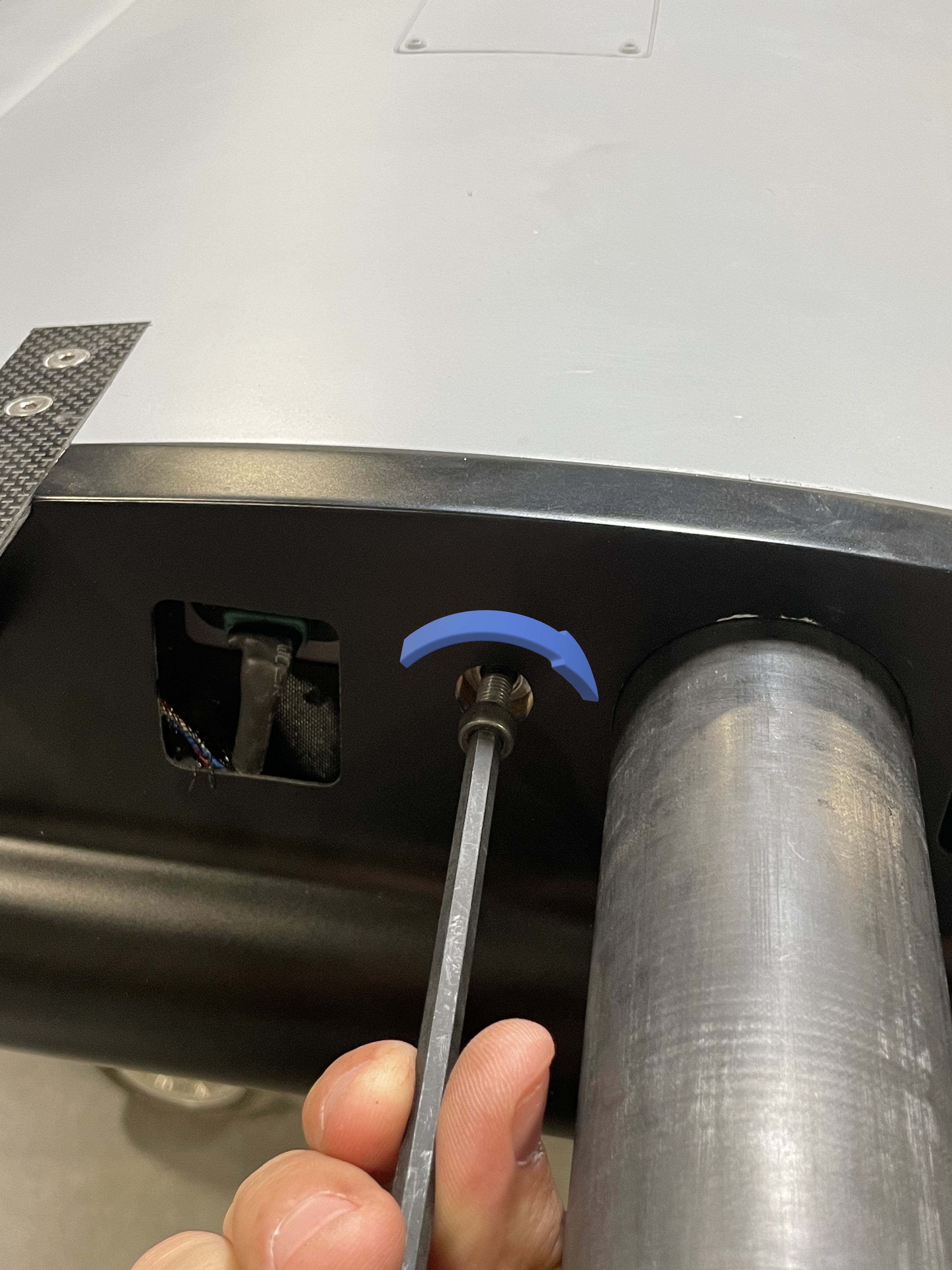
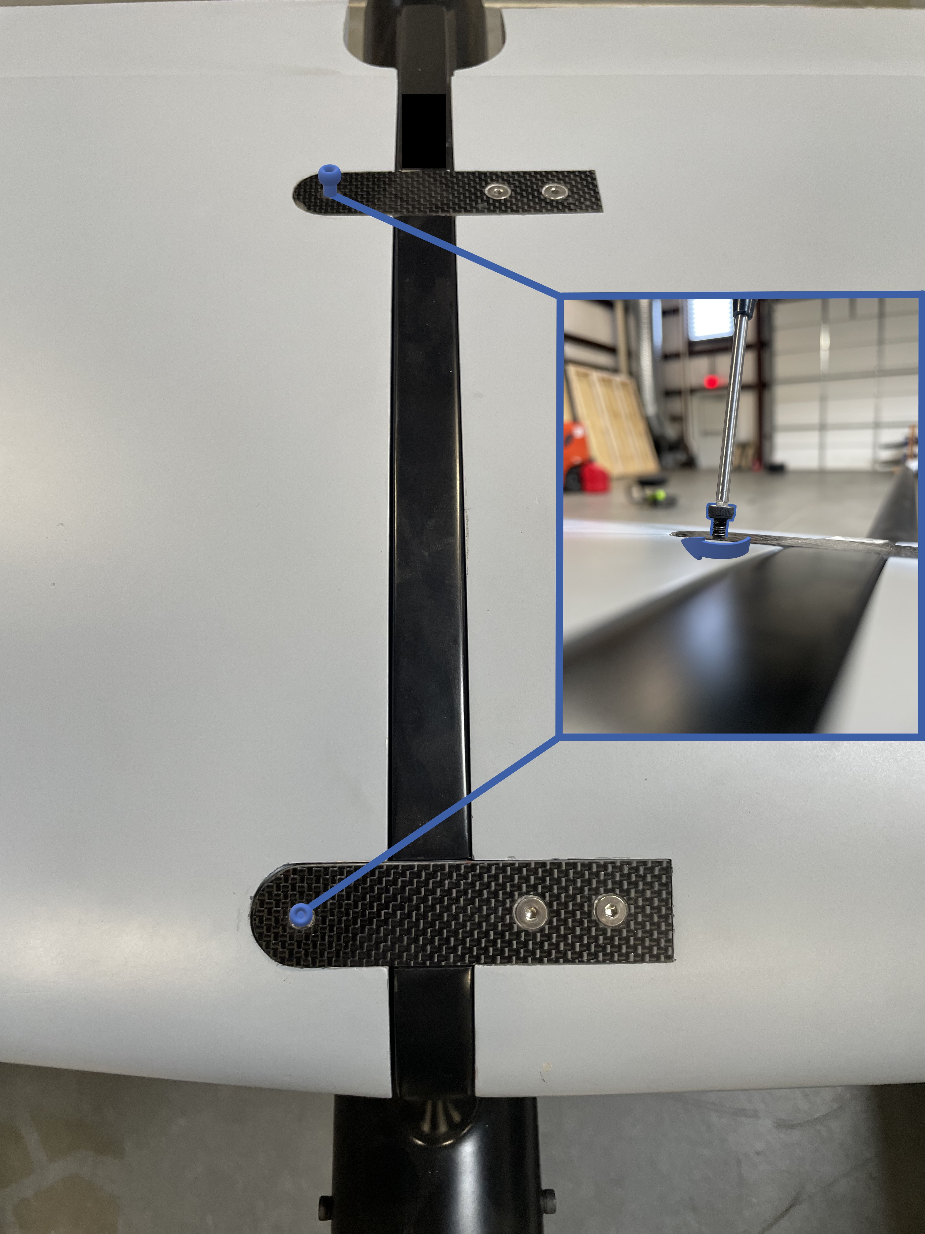
- Fasten the boom to the wing with the single bolt.
- Join the two tail halves and fasten them using the 3mm bolts.
- Slide the Outboard Wings onto the Main Wing Spar, ensure the wing connector is connected before fully seating the wing.
- Secure the Outboard Wings using the supplied bolts.
- Remove the pitot cover.
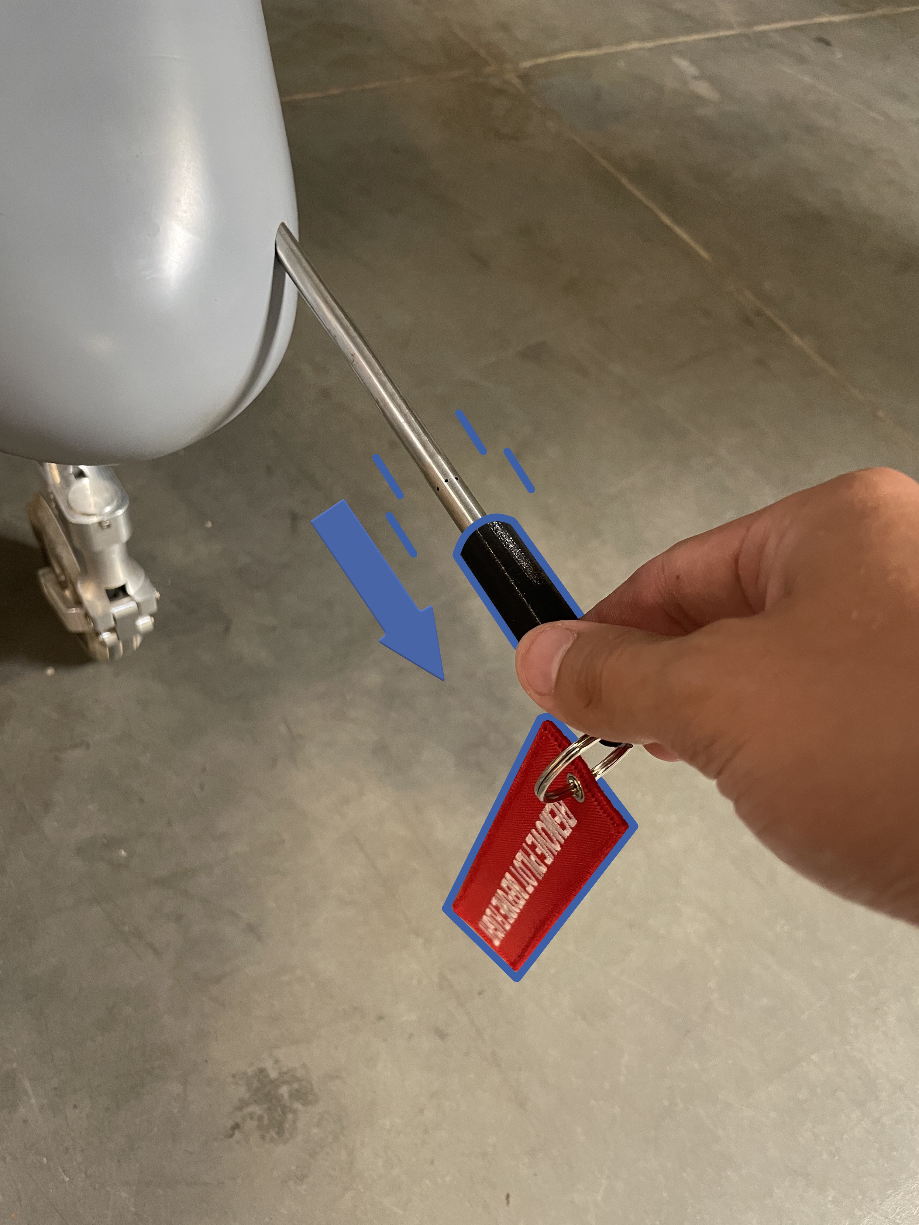
- Extend the pitot tube by gently pulling it away from the aircraft until an audible "click" is heard.
- Install any payload as necessary.
Close the crate after aircraft assembly to prevent dust ingress.
Aircraft - Inspect
IAssemble the aircraft and inspect for any damage and/or irregularities to the airframe, payload, and subcomponents while assembling. Damage may have been caused by previous flights, maintenance, transportation, environmental, or from normal wear and tear. Refer to the Maintenance Section for a more detailed inspection procedure or if damage is found.
- Airframe: Inspect the fuselage, nose cone, wings, and wing fences for cracks or fractures in the composite structure.
- Control Surfaces: Inspect the composite control surface hinges for buckling, cracks, or tears. Check the servo linkages and control horns for damage and ensure they are securely mounted. Slowly move each control surface through their range of motion, ensuring the servo operates smoothly without hitching or skipping.
- Landing Gear: Ensure the landing gear strut, wheels, and brakes are secure. Check the nose wheel steering servo linkage and control horn for damage and ensure both are securely mounted. Slowly turn the nose gear through its range of motion, ensuring the steering servo operates smoothly without hitching or skipping.
- Antennas: Verify all radio, GPS, and payload antennas (if applicable) are secure.
- Propeller: Inspect the propeller for cracks, chips, fractures, etc. Ensure all propeller screws are present. Ensure the propeller is facing the correct way and not reverse.
- Engine Vibration Mounts: Firmly grasp the engine and wiggle it in all directions. The rubber engine mounts should flex but resist excessive movement. Visually check for cracks, missing pieces, or if any mounts are sheared off.
- Engine Standoffs: Firmly grasp each engine vibration mount standoff and ensure it is secure. No twisting or rocking should occur.
- Mufflers: Firmly grasp each muffler and wiggle it in all directions to ensure both are securely attached to the engine. Verify the gasket between each muffler and the engine is present and intact with minimal signs of an exhaust leak.
- Spark Plug Caps: Ensure both spark plug caps are secure.
- Throttle Linkage: Inspect the throttle servo and linkage for damage and mounting security. Slowly move the throttle servo through its full range of motion, ensuring the servo operates smoothly without hitching or skipping.
- Mufflers: Ensure both mufflers are securely attached to the engine. Verify that the gasket between each muffler and the engine is present and intact with no signs of an exhaust leak.
Pitot Tube - Extend
Extend the pitot tube until it snaps into place. Verify that the pitot is not bent and free of obstructions. Verify that the pitot tubing in the fuselage is free of kinks. Verify that the hoses are fully inserted into the backside of the pitot tube itself and the airspeed sensor.
Propeller - Torque
Gradually torque the propeller bolts to 90 in/lbs in a star pattern.
Avionics Battery - Install
Install and the avionics battery within the fuselage and secure it down using the Velcro straps.
Aircraft - Fuel
Fuel the aircraft with the appropriate amount of gasoline needed for the flight, including a 30 minute reserve of 4.5 lbs (0.75 gal).
Refer to the Fueling Section for detailed fueling and mixing instructions.
Weight and Balance - Verify
Verify that the aircraft with payload and ballast is balanced at the 40% CG mark and that the MTOW does not exceed 180 lbs.
Refer to the Weight and Balance Section for detailed balancing instructions.
Telemetry Radio - Connect
Power on and connect the telemetry radio to the GCS computer.
Hand Controller - On
Power on the hand controller. Ensure the correct model is displayed.
Avionics Battery - Connect
Connect the avionics battery.
As soon as the aircraft is on, the autopilot and sensors will begin to initialize. Avoid moving the aircraft during these first few seconds.
Autopilot - Connect
From the Checklist tab in Swift GCS press Connect and choose the appropriate connection type.
Firmware - Check
The GCS will automatically check that the autopilot's firmware is correct and up to date. If this check fails, go to the Settings Tab ⇨ Firmware Upload in Swift GCS to update the firmware.
Refer to firmware update for more information.
Parameter Checks
The GCS will automatically check that the autopilot parameters are correctly configured. If any parameters fail the check please contact info@spektreworks.com. Do not fly.
Old Mission - Clear
The existing mission on the aircraft must be cleared before a new flight. Press the Clear button on the checklist step or go to the Plan Tab ⇨ Clear WP ⇨ Clear mission on the aircraft.
Mission - Create
Create or load a mission from the Plan Tab.
Refer to mission planning for more information on waypoints.
Planned and modified waypoints will appear red in the GCS until uploaded to the autopilot.
Mission - Upload
Press Upload on the checklist step, or go to the Plan Tab ⇨ Upload to upload the mission to the autopilot.
Planned and modified waypoints will appear red in the GCS until uploaded to the autopilot.
Flight Modes - Verify
Navigate to the Settings Tab ⇨ Flight Modes to choose which flight modes are mapped to the hand controller's mode switch. You must save your changes for the new configuration to take effect. Typically the three modes are manual, FBWA, and auto, however this can vary depending on the mission requirements and crew experience. The modes chosen here do not limit which modes are available through the GCS, just the hand controller.
Failsafes - Verify
Navigate to the Settings Tab ⇨ Failsafes to configure your failsafes.
Autopilot - Warmup
The autopilot has an internal heater to hold the IMU at a specific temperature which improves the accuracy of the sensors. Please wait for the IMU to reach the required temperature before proceeding.
Airspeed - Calibrate
This step will walk you through calibrating the airspeed sensor. First shield the pitot tube from any wind with the provided pitot tube cover. Next, press Calibrate on the Checklist Tab. Remove the pitot tube cover before testing. To conduct the test first cover the drain port with your fingertip. Next, tap and hold the pitot tube opening with your other fingertip while someone monitors the GCS. This action will trap air, increasing the sensor pressure reading. If enough air is trapped, the GCS progress bar will advance, and the step will complete automatically.
If the test fails, ensure the drain port is completely covered and retry by tapping harder. Do not wear gloves when blocking the drain port or pitot tube. If the test continues to fail, there may be a leak in the pitot-static system, a cut hose, or one of hoses may not be fully seated in a quick-disconnect fitting.
Compass - Check
Verify that the nose of the aircraft is pointing in the same direction as shown in the GCS. If the two headings disagree, you may need to perform a compass calibration.
Mode - Manual
Using the hand controller, set the flight mode swith to Manual.
Control Surfaces - Enable
Press Unlock in aircraft commands to enable control surfaces.
Manual Control - Check
Using the hand controller, move the control surfaces through their full range of motion while verifying the responses are correct.
Mode - FBWA
Using the hand controller, set the flight mode switch to FBWA.
FBW Response - Check
Test that the control surfaces respond correctly to physically moving the aircraft. The control surfaces should oppose the movement in each direction. For example, when one wing is lifted up, the elevons should be trying to return the aircraft to level. The same applies to pitch. By moving the aircraft you are testing that the autopilot is responding correctly to attitude upsets.
Mode - Manual
Using the hand controller, set the flight mode swith to Manual.
Brakes - Test
Test the brake function using the hand controller.
Hatches - Secure
Install and secure the canopy and center wing hatch. Ensure all other hatches are secure.
Slide the front canopy tab into the front of the fuselage, pull the rear sides of the canopy outward and lower the rear of the canopy into position. Secure using the quarter turn fasteners.
No Warnings - Verify
Ensure there are no warnings before starting the engine. All warnings must be resolved. Warnings are displayed in the GCS message panel.
Refer to the Warnings Section for a detailed description of warnings, possible causes, and corrective actions.